Transmitted X-ray data acquisition system and X-ray computed tomography system

a technology of computed tomography and data acquisition system, which is applied in the field of transmission x-ray data acquisition system and computed tomography system, can solve the problems of inability to determine the conduction time relative to the intermediate scanning position, excessive x-ray radiation, and large dose, and achieve the effect of controlling the quality of the image produced based on transmitted x-ray data

Active Publication Date: 2006-01-17
GE MEDICAL SYST GLOBAL TECH CO LLC
View PDF9 Cites 29 Cited by
  • Summary
  • Abstract
  • Description
  • Claims
  • Application Information

AI Technical Summary

Benefits of technology

[0022]Preferably, the target image SD can be manually adjusted so that the quality of an image produced based on transmitted X-ray data can be controlled.
[0023]Preferably, the dose is adjusted based on a tube current flowing through the X-ray tube. In this case, the dose adjustment is easy to do.
[0030]Preferably, a detector having a plurality of rows of detecting elements, each of which has a plurality of X-ray detecting elements arrayed in a direction in which the fan-shaped X-ray beam spreads, arranged in the direction of the thickness of the fan-shaped X-ray beam is adopted as the X-ray detector. In this case, helical scanning to be performed with the helical scan pitch set to a large value can be efficiently achieved

Problems solved by technology

Consequently, a total dose is too large and excessive X-rays are irradiated.
The product of a tube current by a conduction time determined relative to the intermediate scanning position is not always appropriate for the other positions.

Method used


Image

  • Transmitted X-ray data acquisition system and X-ray computed tomography system
  • Transmitted X-ray data acquisition system and X-ray computed tomography system
  • Transmitted X-ray data acquisition system and X-ray computed tomography system

Examples


Embodiment Construction

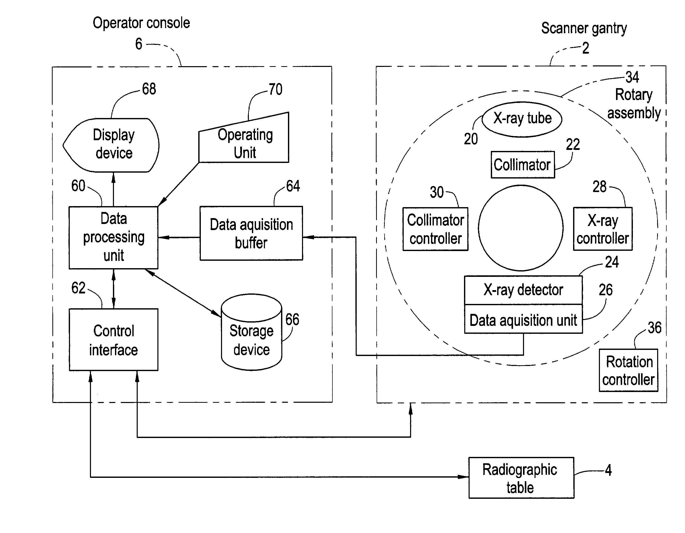
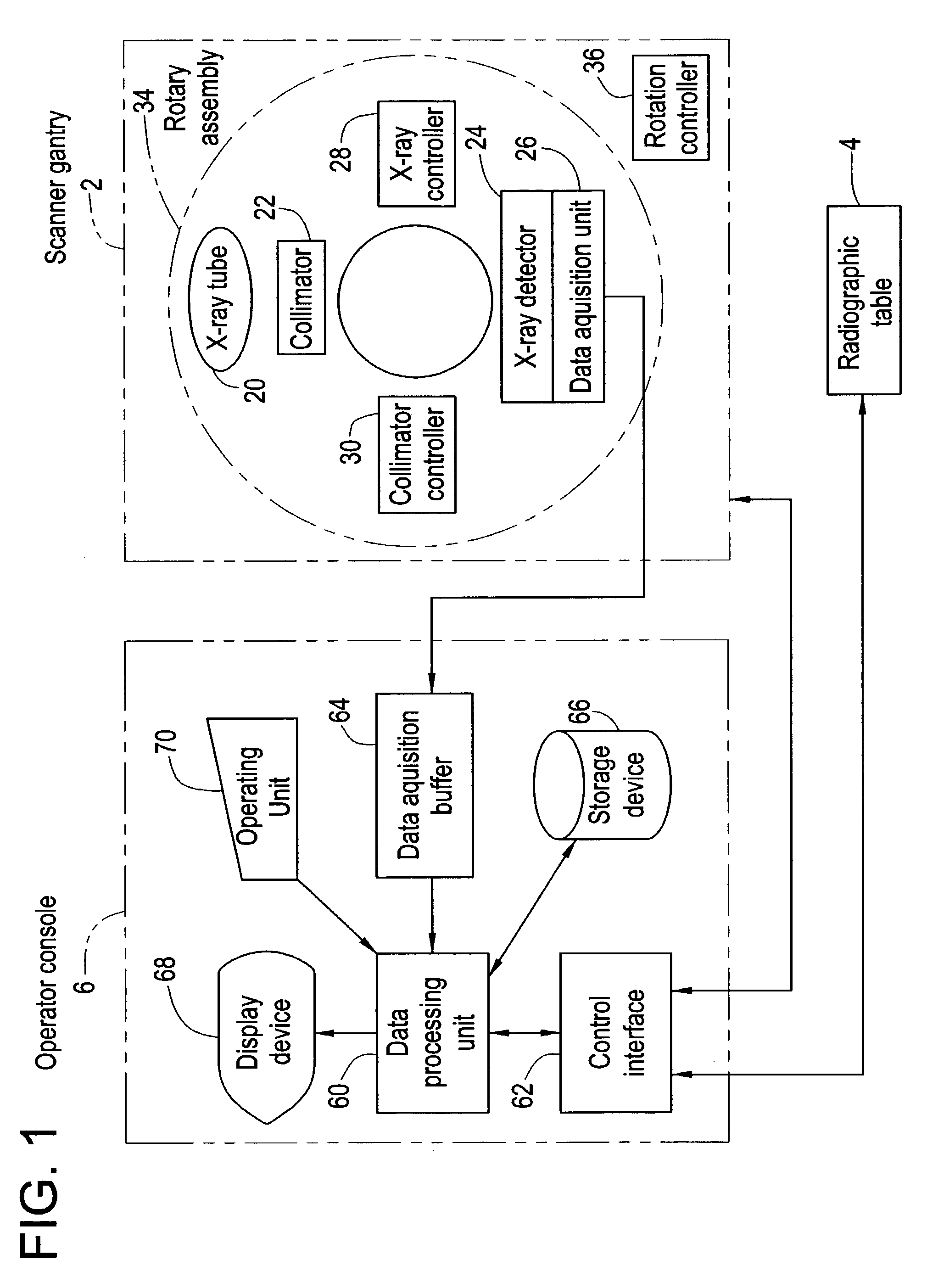
[0054]An embodiment of the present invention will be described with reference to the drawings below. FIG. 1 is a block diagram showing an X-ray computed tomography (X-ray CT) system. The present system is an example of an embodiment of the present invention. The configuration of the present system provides an example of an embodiment of an X-ray computed tomography system in which the present invention is implemented. The actions of the present system provide an example of an embodiment of an X-ray computed tomography method in which the present invention is implemented.

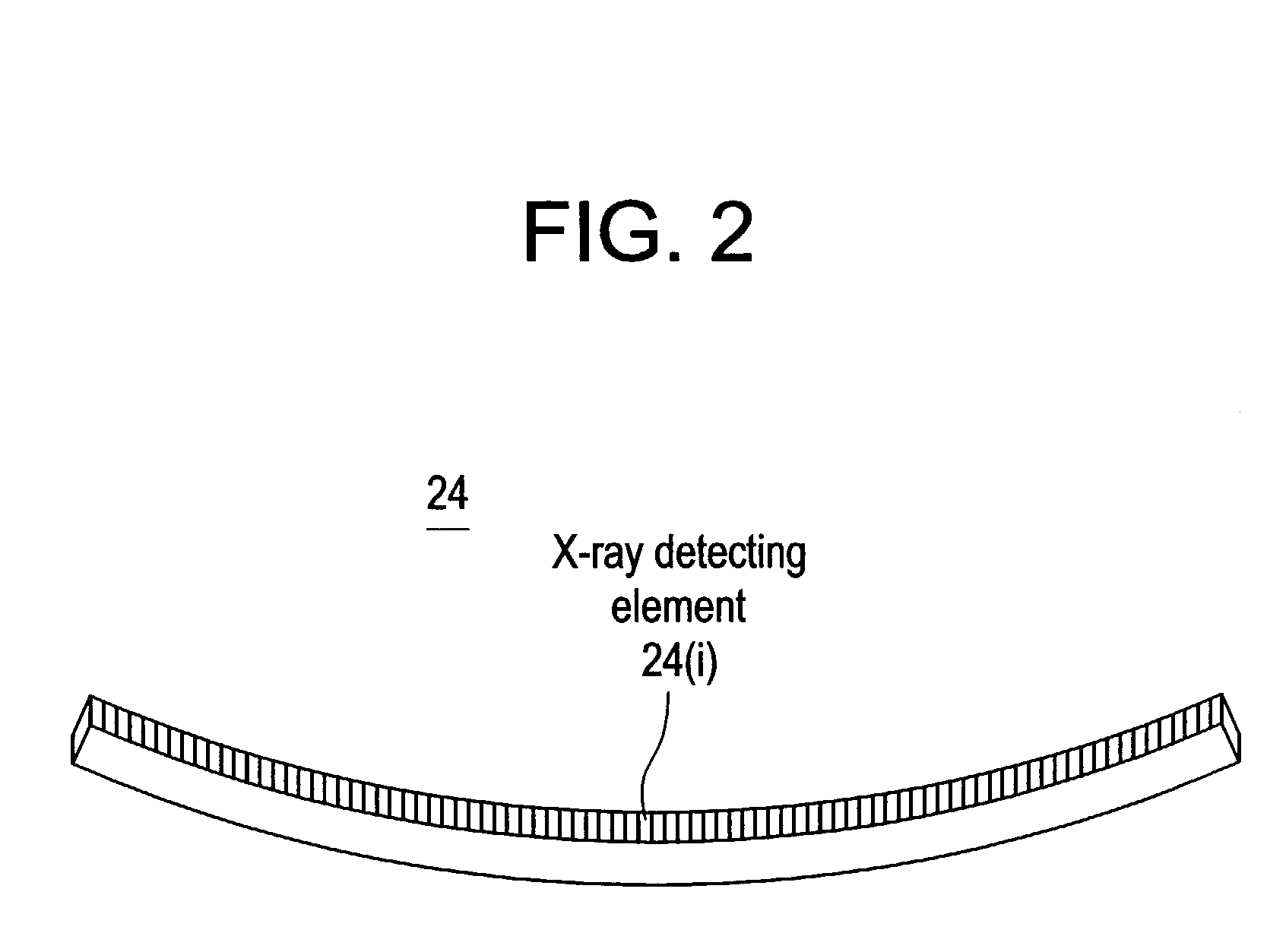
[0055]As shown in FIG. 1, the present system consists mainly of a scanner gantry 2, a radiographic table 4, and an operator console 6. The scanner gantry 2 includes an X-ray tube 20. X-rays radiated from the X-ray tube 20 and not shown are recomposed into a fan-shaped X-ray beam, that is, a fan beam by means of a collimator 22, and irradiated to an X-ray detector 24. The X-ray tube 20 and collimator 22 constitute an ...


PUM

PropertyMeasurementUnit
angle of rotationaaaaaaaaaa
angleaaaaaaaaaa
angleaaaaaaaaaa

Abstract

An object of the present invention is to acquire transmitted X-ray data by irradiating X-rays of appropriate doses determined for the portions of a section containing the major axis and the portions thereof containing the minor axis respectively. An X-ray irradiating / detecting device consists mainly of an X-ray irradiator that includes an X-ray tube and irradiates a fan-shaped X-ray beam, and an X-ray detector that has a plurality of X-ray detecting elements arrayed in a direction in which the fan-shaped X-ray beam spreads and that is opposed to the X-ray irradiator with an object of imaging between them. The X-ray irradiating / detecting device is rotated about the object in order to acquire transmission X-ray data stemming from a plurality of views. At this time, the dose of the X-ray beam is differentiated between predetermined angular ranges of a section of the object shaped like an oval, which extend with the minor axis of the oval section as a centerline, and the other angular ranges.

Description

[0001]This application claims the benefit of Japanese Application No. 2002-088003 filed Mar. 27, 2002.BACKGROUND OF THE INVENTION[0002]The present invention relates to a transmitted X-ray data acquisition system and an X-ray computed tomography system. More specifically, the present invention relates to a system for acquiring transmitted X-ray data based on which an X-ray tomographic image is produced, and an X-ray computed tomography system for producing the tomographic image on the basis of the acquired transmitted X-ray data.[0003]In X-ray computed tomography systems, an X-ray irradiating / detecting device acquires transmitted X-ray data that represents X-rays transmitted by an object of imaging, and a tomographic image of the object is produced (reconstructed) based on the transmitted X-ray data. The X-ray irradiator irradiates an X-ray beam that spreads (has a width large enough) to cover a tomographic layer of the object or a radiographic section thereof and has a thickness in ...

Claims


Application Information

Patent Timeline
Patent Type & Authority Patents(United States)
IPC IPC(8): A61B6/00A61B6/03A61B6/02G01N23/04G06T1/00
CPCG01N23/046G01N2223/419A61B6/027
Inventor HORIUCHI, TETSUYA
Owner GE MEDICAL SYST GLOBAL TECH CO LLC
Why Eureka
Try Eureka