Method and apparatus for blow molding large reinforced plastic parts

a technology of reinforced plastic parts and blow molding techniques, which is applied in the direction of manufacturing tools, vehicular safety arrangements, vehicle cleaning, etc., can solve the problems of limited ability to blow mold large complex parts, unpractical blow molding techniques, and complex parts

Inactive Publication Date: 2006-01-24
MAGNA INT OF AMERICA
View PDF90 Cites 25 Cited by
  • Summary
  • Abstract
  • Description
  • Claims
  • Application Information

AI Technical Summary

Benefits of technology

[0010]In another embodiment, there is provided a hollow, sealed front end bumper that comprises at least one thermoplastic material and reinforcement particles dispersed within the at least one thermoplastic material. The reinforcement particles comprise less than 15% of a total volume of the bumper, at least 50% of the reinforcement particles have a thickness of less than about 20 nanometers, and at least 99% of the reinforcement particles having a thickness of less than about 30 nanometers. A fluid consuming component is constructed and arranged to be mounted on and used by the motor vehicle. A conduit communicates the fluid consuming component with the sealed interior of the hollow bumper, thus permitting said hollow sealed bumper to serve as a fluid reservoir for the fluid consuming component.

Problems solved by technology

As a result, some of these parts have become quite complex.
The usefulness of blow molding techniques for forming such parts has not been practical due to the structural characteristics of the plastic material conventionally used in blow molding techniques.
That is, the ability to blow molding large complex parts is limited by the fact that the parts produced can be only so large or so thin before the parts lose their structural integrity and impact resistance.
However, such reinforcement cannot be used effectively in blow molding operations, because the glass fibers limit parison expansion characteristics and also have a deleterious effect on the blow molding assembly itself.
Furthermore, such reinforcement has a deteriorating effect on impact resistance of the part.

Method used


Image

  • Method and apparatus for blow molding large reinforced plastic parts
  • Method and apparatus for blow molding large reinforced plastic parts
  • Method and apparatus for blow molding large reinforced plastic parts

Examples


Embodiment Construction

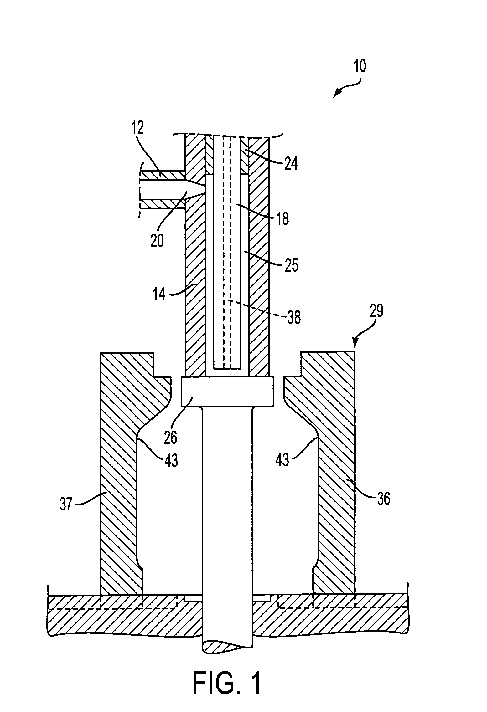
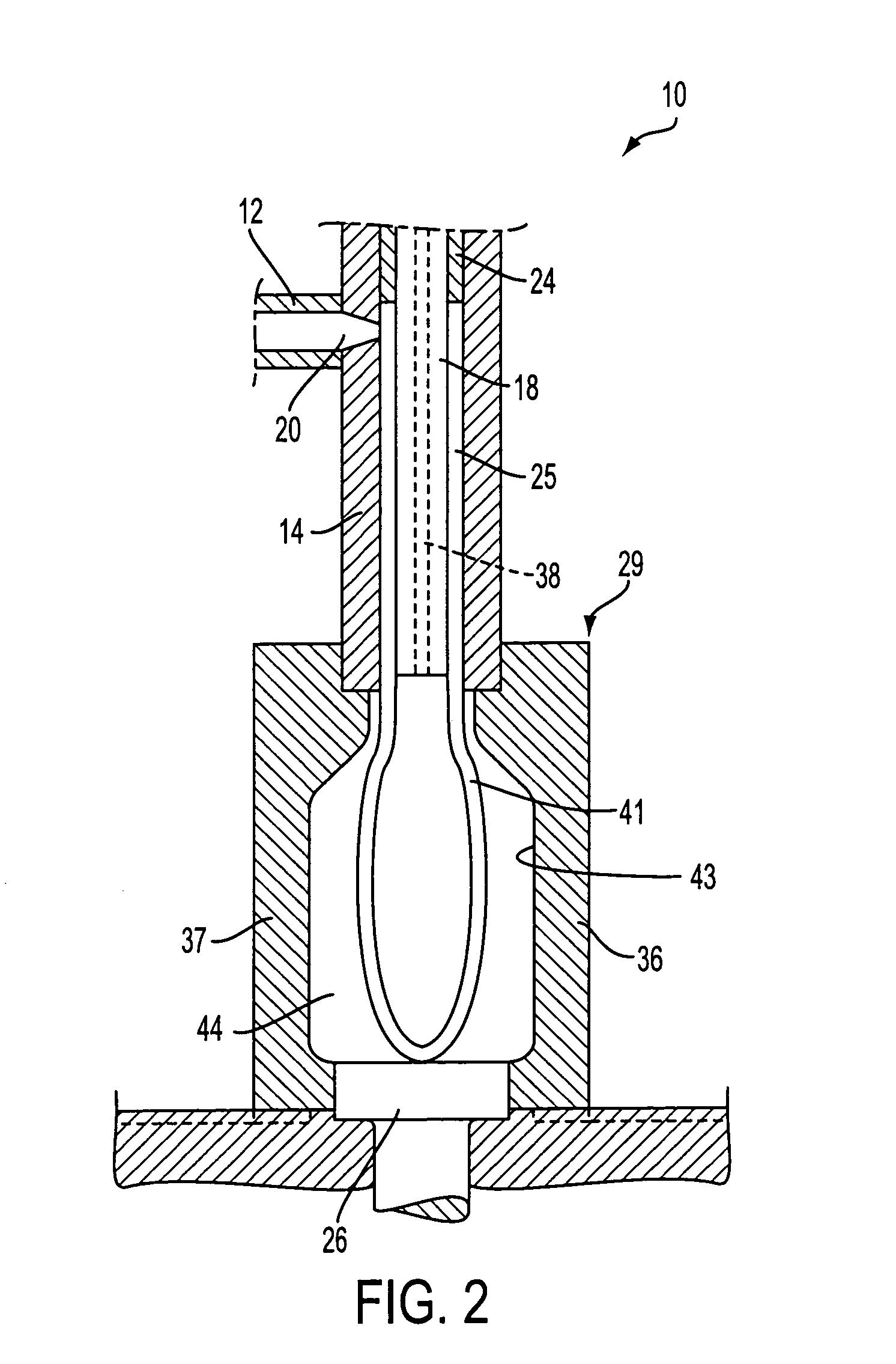
[0019]Illustrated in FIG. 1 is a blow molding assembly, generally indicated at 10, in accordance with the present invention. The assembly 10 includes an extruder nozzle 12 connected with a tubular head assembly 14. The tubular head assembly 14 is provided with an internal tubular core 18. An ejecting mechanism 24 is disposed in the space between the tubular head assembly 14 and the core 18.

[0020]A hot plastic melt 20 is supplied through an extruder nozzle 12 into the tubular head assembly 14. A hot plastic preform 25 is produced in the cavity between the core 18 and the assembly 14. During this process the lower end of the head assembly 14 is firmly engaged by a movable base plate 26, constituting the upper portion of a hydraulic ram structure, for sealing the lower end of the cavity between core 18 and head assembly 14. The blow molding assembly further comprises a mold assembly 29, which has internal mold surfaces defining a die cavity. The die surfaces correspond to the external ...


PUM

PropertyMeasurementUnit
thicknessaaaaaaaaaa
thicknessaaaaaaaaaa
weightaaaaaaaaaa

Abstract

A method for molding large parts, comprises the steps of providing a reinforced plastic melt comprising at least one thermoplastic material and reinforcement particles dispersed within the at least one thermoplastic material, the reinforcement particles comprising less than 15% of a total volume of the plastic melt, at least 50% of the reinforcement particles having a thickness of less than about 20 nanomenters, and at least 99% of the reinforcement particles having a thickness of less than about 30 nanometers; communicating a tubular formation of the plastic melt to a mold assembly having a mold cavity defined by mold surfaces, the mold surfaces corresponding to a configuration of the part to be molded; applying pressurized gas to an interior of the tubular formation to expand the tubular formation into conformity with the mold surfaces; and solidifying the plastic melt to form the part; and removing the part from the mold assembly.

Description

GOVERNMENTAL SUPPORT AND INTEREST[0001]The invention in this patent was made with Governmental support under Cooperative Agreement No. 70NANB7H3028 awarded to the Dow Chemical Company and Decoma International of America, Inc. (formerly Magna International of America, Inc.), project ID 1997-02-0047B, project name “NANOCOMPOSITES—NEW LOW COST / HIGH STRENGTH MATERIALS FOR AUTOMOTIVE PARTS,” awarded Sep. 30, 1997 by the United States Department of Commerce, National Institute of Standards and Technology, Advanced Technology Program. The Government has certain rights in this invention.[0002]This application is the National Phase of International Application No. PCT / US99 / 29991, filed Dec. 17, 1999, published as WO 00 / 37239, which claims priority from U.S. Provisional Patent Application Ser. No. 60 / 113,064, filed Dec. 21, 1998, the contents of all of which are incorporated herein by reference.BACKGROUND OF THE INVENTION[0003]The present invention relates to blow molding methods and apparatu...

Claims


Application Information

Patent Timeline
Patent Type & Authority Patents(United States)
IPC IPC(8): B23P17/00
CPCB29C49/0005B60S1/50B62D25/084B62D29/043B29C49/04Y10T29/49622B29C2791/001B29C2793/009B29K2105/12B29K2105/162B29L2031/18B29L2031/3044B29L2031/747B60R2019/184Y10T29/4998
Inventor WILSON, PHILLIP S.
Owner MAGNA INT OF AMERICA
Why Eureka
Try Eureka