Knitted surface fastener

Active Publication Date: 2006-01-24
YKK CORP
View PDF8 Cites 70 Cited by
  • Summary
  • Abstract
  • Description
  • Claims
  • Application Information

AI Technical Summary

Benefits of technology

[0011]Accordingly, an object of the present invention is to provide a knitted surface fastener which eliminates necessity of b

Problems solved by technology

As a result, the entire base fabric hardens so that gaps between stitches or weave patterns are covered with resin except the aforementioned Japanese Utility Model Publication No. 2563369 disclosing a net-like base fabric, and as a consequence, ventilation becomes poor.
However, plural loop yarns are not knitted into the same course on the same wale formed with the chain knitting yarns but a single loop yarn is knitted into each course and therefore, the engaging elements are likely to loose out.
Although, according to the Japanese Patent

Method used


Image

  • Knitted surface fastener
  • Knitted surface fastener
  • Knitted surface fastener

Examples


first embodiment

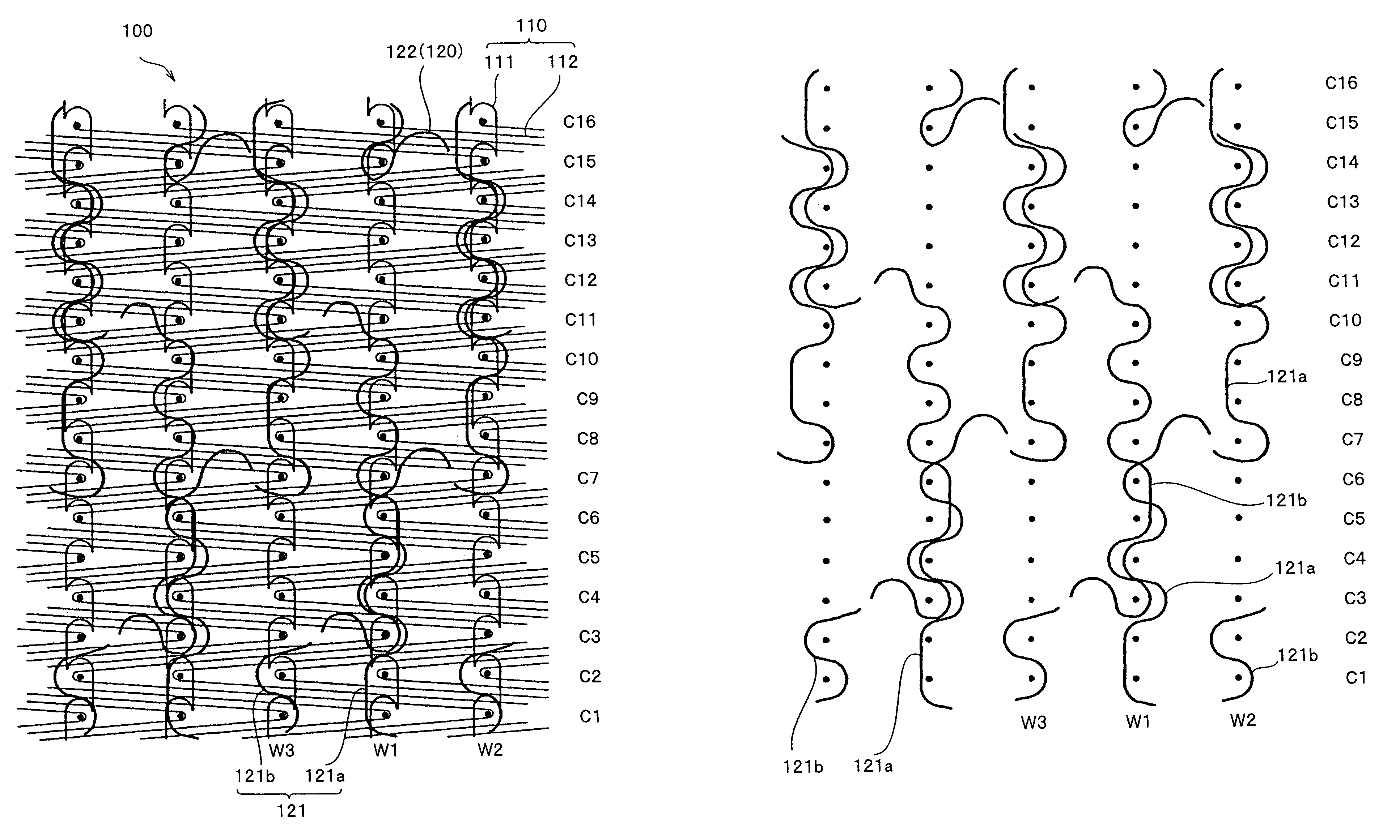
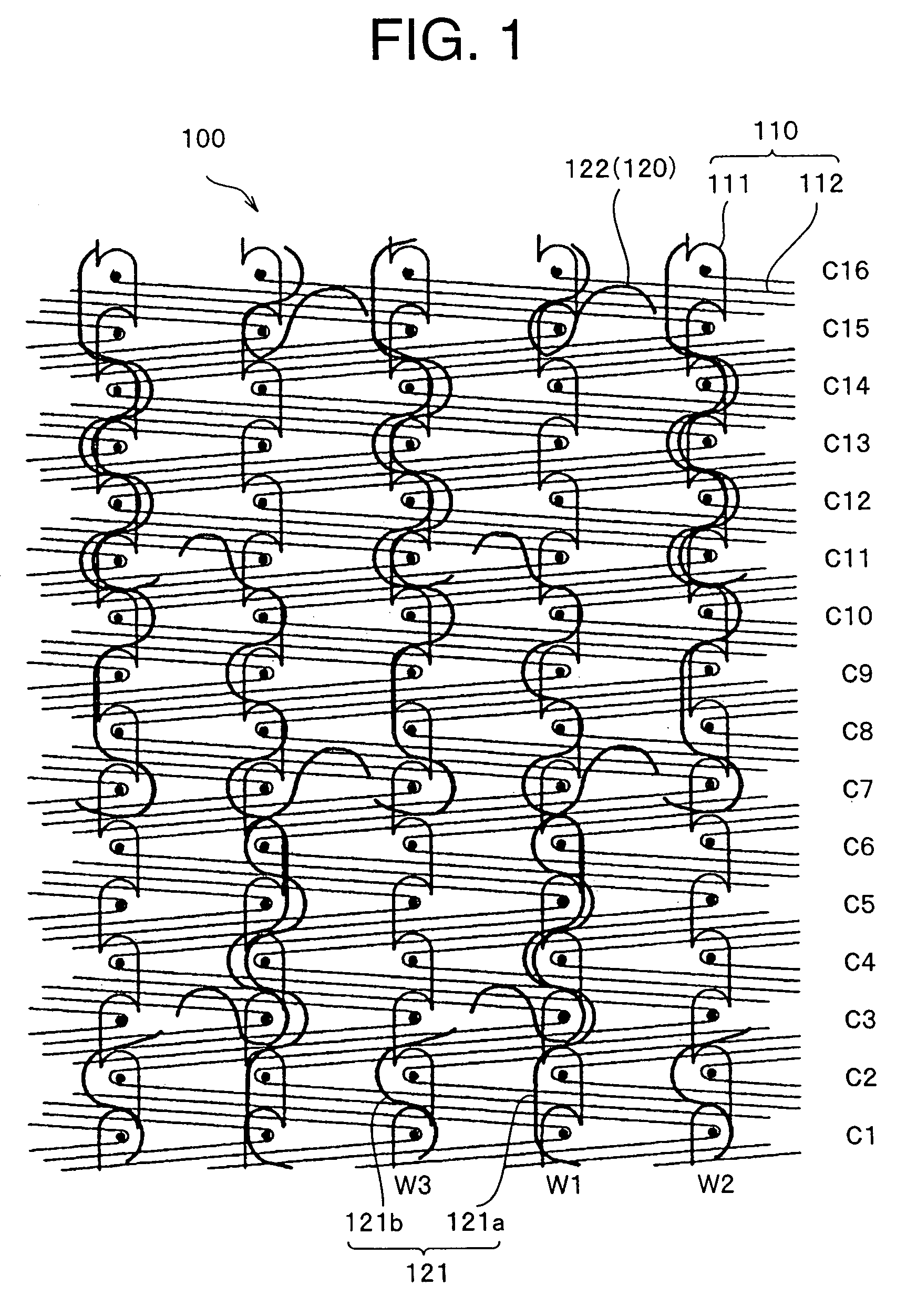
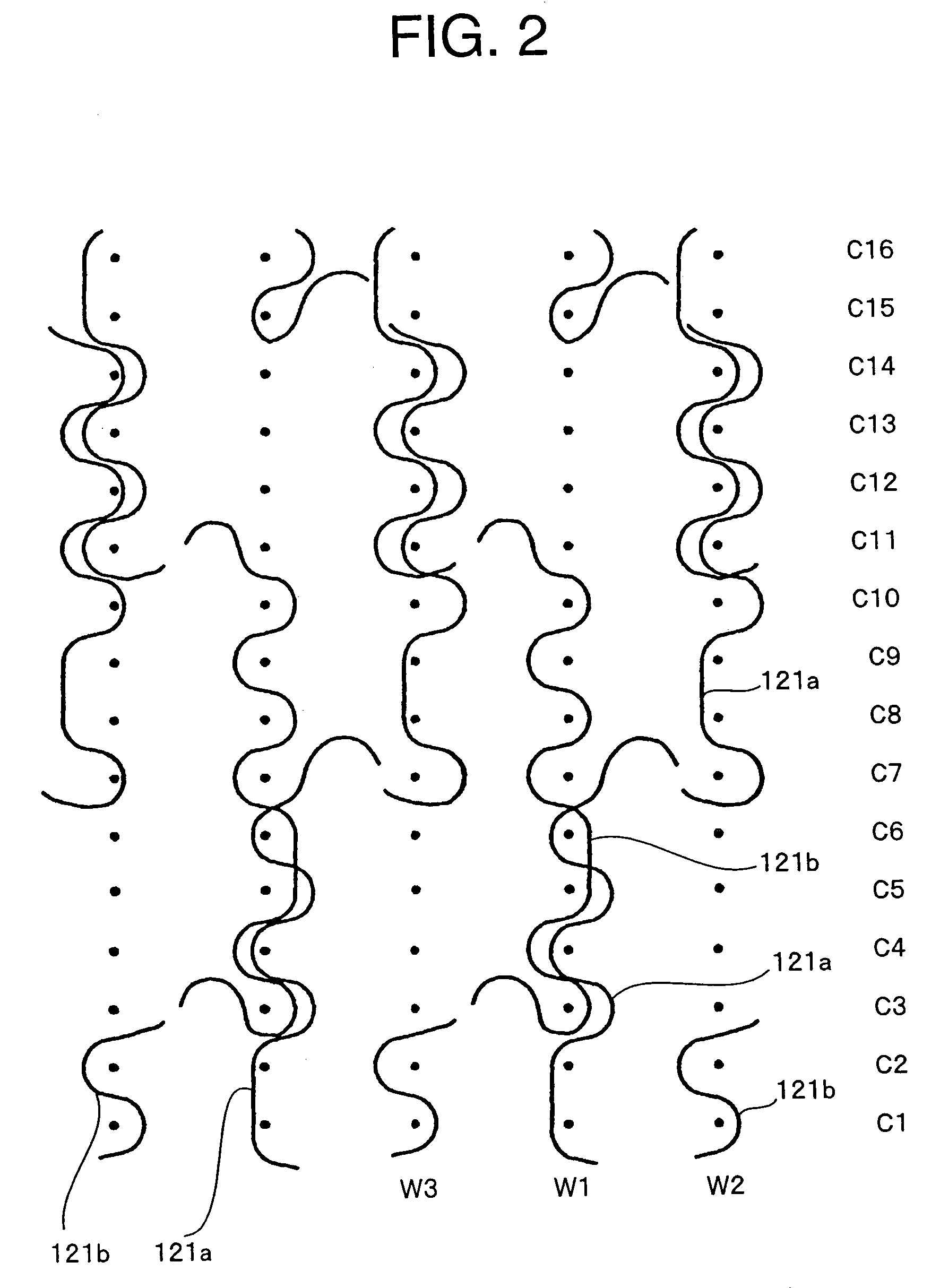
[0030]FIG. 1 shows an entire structure diagram of the male knitted surface fastener according to a first embodiment of the present invention. FIG. 2 shows an independent structure of engaging element forming yarns in the first embodiment. FIG. 3 schematically shows a knitting construction of an entire surface fastener. Although in FIG. 3, sizes of composition yarns are changed or stitches and its densities are expressed extremely large in order to facilitate understanding, actually, the sizes of the composition yarns are arbitrary. Further, since the densities of the stitches are high, gaps formed between stitches are extremely small.

[0031]A male surface fastener 100 of this embodiment is composed of a base fabric 110 and hooks 120 protruded from an entire surface of the base fabric 110. The base fabric 110 is constituted of chain knitting yarns 111 having 1-0 / 0-1 structure which forms a wale W, and weft in-laid yarns 112 having 0-0 / 5-5 structure which run in a zigzag shape across f...

second embodiment

[0038]FIG. 4 is a structure drawing showing an entire structure of a knitted surface fastener 100 according to a second embodiment of the present invention. According to this embodiment also, a base fabric 110 is composed of chain knitting yarns 111 having 1-0 / 0-1 structure forming wales W and weft in-laid yarns 112 having 0-0 / 5-5 structure running across five wales W in the zigzag shape, each of the weft in-laid yarn being inserted into stitches of the chain knitting yarns 111. At a same time when the base fabric 110 is formed, loops are formed by knitting an engaging element forming yarns 121 into the same base fabric. A side portion of each of the loops is cut out during or after knitting so as to form a hook 120. FIG. 5 is a knitting structure drawing of two engaging element forming yarns 121a, 121b excluding the knitting structure of the base fabric 110. FIG. 6 schematically shows a knitting construction of a knitted surface fastener of this embodiment. Although sizes of knitti...

third embodiment

[0041]FIG. 7 shows a third embodiment of a knitted surface fastener 100 of the present invention. FIG. 7 shows only knitting structures of first and second engaging element forming yarns 121a, 121b while the knitting structure of a base fabric 110 is omitted because its is same as that of the first embodiment. According to this embodiment, the knitting structure of the first engaging element forming yarn 121a is 0-0 / 1-1 / 0-0 / 2-2 / 1-1 / 2-2 and the knitting structure of the second engaging element forming yarn 121b is 1-1 / 2-2 / 0-0 / 1-1 / 0-0 / 2-2. That is, the first and second engaging element forming yarns 121a, 121b are deviated by a single course in a course direction and inserted in a doubled manner in the zigzag shape into a sinker loop of each chain stitch formed in adjoining three courses on a same wale.

[0042]Therefore, the first and second engaging element forming yarns 121a, 121b are inserted into chain stitches of adjoining two courses in a double manner in the zigzag shape on a wal...


PUM


Abstract

The invention provides a knitted surface fastener made of warp knitted fabric, which eliminates necessity of resin coating for fixing a base portion of a pile loop and fusion between yarns, securing flexibility and ventilation proper to knitted fabric wherein, in a base fabric of a surface fastener, wales are formed with at least chain knitting yarns and the respective wales are connected including at least weft in-laid yarns, engaging element loops are formed of first and second engaging element forming yarns striding over two or more wales and the respective engaging element forming yarns are knitted into at least three adjoining courses on a same wale in a zigzag shape, at this time, the first and second engaging element forming yarns are knitted into adjoining same stitches of at least two or more courses of the same wale in the zigzag shape.

Description

BACKGROUND OF THE INVENTION[0001]1. Field of the Invention[0002]The present invention relates to a surface fastener obtained by warp knitting and more particularly to a knitted surface fastener that secures flexibility characteristic to knitted fabric without necessity of back coating.[0003]2. Description of the Related Art[0004]In a surface fastener made of fiber, engaging element forming yarns are woven or knitted in so as to form a plurality of loops on a surface of a base fabric at a same time when the base fabric is woven or knitted. Each of the loops serves as a female engaging element as it is or it forms a hook-like or mushroom-shaped male engaging element by cutting a part thereof. In order to prevent the engaging element from loosing out of the base fabric in the surface fastener obtained by weaving or knitting, a surface opposite to the surface having the engaging elements is coated with resin or so-called back coating is performed so as to bond the base fabric with the e...

Claims


Application Information

Patent Timeline
IPC IPC(8): D04B21/02
CPCA44B18/0023D04B21/10D04B21/02D10B2501/0632A44B18/00Y02P70/62
Inventor OKAWA, MITSUHISANAKAYAMA, EIJIISHIHARA, MITSUTOSHI
Owner YKK CORP
Why Eureka
Try Eureka