Fuel pressure relief valve

a technology of fuel pressure relief valve and fuel delivery system, which is applied in the direction of liquid fuel feeder, fuel injecting pump, machine/engine, etc., can solve the problems of fuel leakage, fuel leakage from the fuel delivery system has a negative impact on the efforts of automotive manufacturers, and fuel leakage typically occurs, so as to minimize evaporative emissions and minimize fuel pressure buildup.

Inactive Publication Date: 2006-01-24
FORD GLOBAL TECH LLC
View PDF29 Cites 35 Cited by
  • Summary
  • Abstract
  • Description
  • Claims
  • Application Information

AI Technical Summary

Benefits of technology

[0008]A fuel pressure relief valve is provided to minimize fuel leakage and evaporative emissions during diurnal cycles by preventing pressure buildup as the temperature of the fuel system rises. One version of the fuel pressure relief valve includes an excess flow valve and a back pressure relief valve. (In the art, relief valves and pressure regulators generally have similar functions and thus are considered herein to be alternative terminology.) The excess flow valve seals when fuel flow is generated by the fuel pump during operation of the automotive vehicle. When the automotive vehicle is turned off and the fuel pump is stopped, the excess flow valve unseals after the temperature cools and the fuel pressure drops. Thereafter, during diurnal cycles, a back pressure relief valve prevents pressure buildup by unsealing when the pressure exceeds a release pressure and re-sealing when below that pressure, thereby releasing a small amount of fuel to the fuel tank. One advantage of the fuel pressure relief valve is that it can be employed as an inexpensive passive valve without the need for electronics or a control system.

Problems solved by technology

One source of emissions is fuel leakage from the fuel delivery system.
As a result, fuel leakage from the fuel delivery system has a negative impact on automotive manufacturers efforts to satisfy the evaporative emissions standards currently issued and any future standards that might be issued by the Environmental Protection Agency and the California Air Resources Board.
Fuel leakage typically occurs because the fuel delivery system remains pressurized after the automotive vehicle is turned off.
However, because the fuel remains pressurized, fuel leaks from various components in the fuel delivery system.
One common source of leakage is through the fuel injectors, which are used in most automotive fuel systems.
Fuel can also leak by permeation through various joints in the fuel delivery system.
Fuel leakage is particularly exacerbated by diurnal temperature cycles.
In conjunction with this temperature rise, the pressure in the fuel delivery system also increases, which results in leakage through the fuel injectors and other components.
This temperature cycle repeats itself each day, thus resulting in a repeated cycle of fuel leakage and evaporative emissions.

Method used


Image

  • Fuel pressure relief valve
  • Fuel pressure relief valve
  • Fuel pressure relief valve

Examples


Embodiment Construction

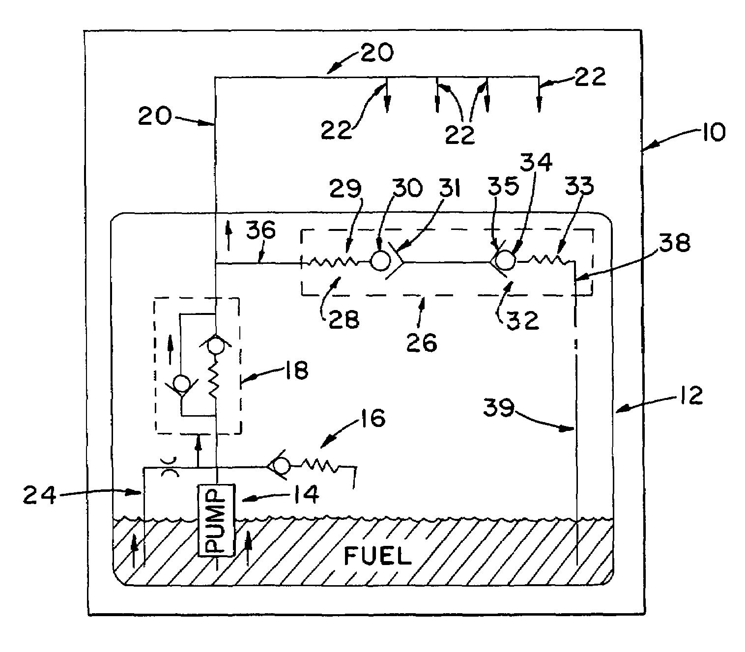
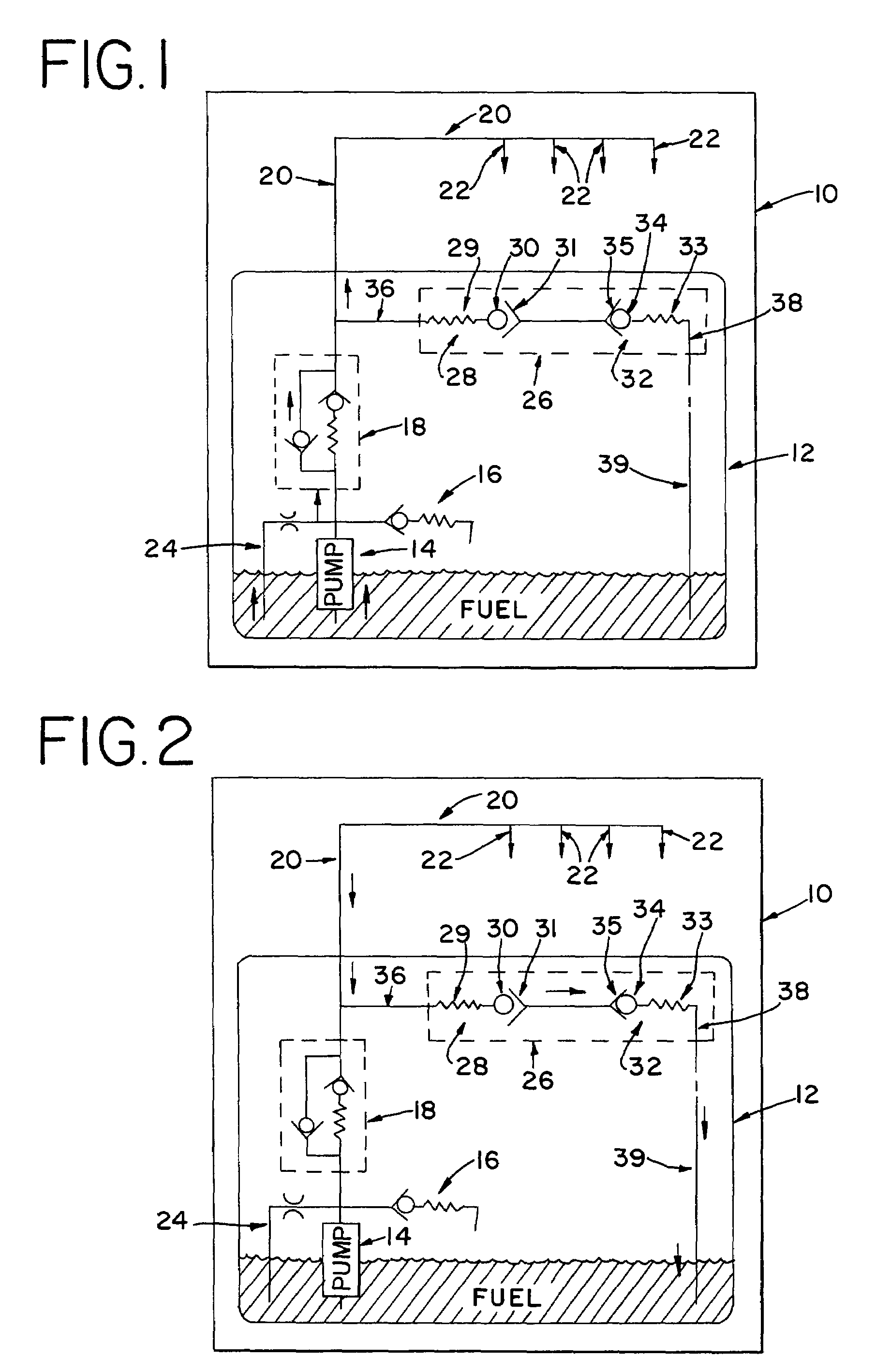
[0027]Turning now to the drawings, and particularly to FIGS. 1 and 2, a typical fuel delivery system 10 is shown. The fuel delivery system 10 is representative of typical fuel delivery systems used on automotive vehicles and includes a fuel tank 12, a fuel pump 14, a pump pressure relief valve 16, a parallel pressure relief valve 18, a fuel rail 20, and a series of fuel injectors 22. A typical parallel pressure relief valve consists of a 2.5 psi check valve and a 55 psi pressure relief valve. As those skilled in the art will readily appreciate, during operation the fuel pump 14 supplies fuel to the fuel manifold, or fuel rail 20, through the parallel pressure relief valve 18. The fuel is then injected into the intake manifold (not shown) of the engine through the fuel injectors 22. When the automotive vehicle is turned off, the fuel is maintained in a pressurized state in the fuel rail 20 by the parallel pressure relief valve 18. As described above, the pressurized fuel in the fuel ...


PUM


Abstract

A fuel pressure relief valve is provided to minimize evaporative emissions due to fuel leakage through the fuel injectors. The fuel pressure relief valve is sealed during operation to prevent flow through the valve. When the automotive vehicle is not operating and the temperature has cooled, the valve unseals. Thereafter, temperature rises that would otherwise result in pressure buildup are prevented.

Description

[0001]This application claims the benefit of U.S. Provisional Application No. 60 / 462,974, filed Apr. 15, 2003.BACKGROUND[0002]The present invention relates generally to fuel delivery systems, and more particularly to a fuel valve.[0003]Several known government standards exist for measuring the amount of evaporative emissions that an automotive vehicle emits during time periods of non-operation. Examples of such government standards are those issued by the Environmental Protection Agency and the California Air Resources Board. In order to measure evaporative emissions, one common test involves operating an automotive vehicle until the vehicle reaches normal operating temperature. The automotive vehicle is then turned off and moved into a sealed chamber. Next, a set of chemical sensors measure the amount and type of emissions released by the vehicle over a time period of several days. During the time period that the emissions are being measured, typical environmental conditions are du...

Claims


Application Information

Patent Timeline
Patent Type & Authority Patents(United States)
IPC IPC(8): F02M37/04F02M55/00F02M69/46F02M69/54
CPCF02M37/0029F02M69/54F02M69/462F02M55/002
Inventor PURSIFULL, ROSS D.GIMBY, DAVID R.
Owner FORD GLOBAL TECH LLC
Why Eureka
Try Eureka