Guide tube

Active Publication Date: 2006-01-24
OLYMPUS CORP
View PDF13 Cites 204 Cited by
  • Summary
  • Abstract
  • Description
  • Claims
  • Application Information

AI Technical Summary

Benefits of technology

[0013]The guide tube is long enough to reach the stomach wall through the mouth and esophagus. The distance between the two balloons corresponds to the thickness of the stomach wall. Consequently, the guide tube can be fixed to the stomach wall easily and surely.
[0014]According to another aspect of the present invention, there is provided a flexible guide tube which guides an endoscope or a therapeutic device into an abdominal cavity through the mouth

Problems solved by technology

However, since the therapeutic treatment is performed through a narrow tubular cavity, only a portion in the tubular cavity can be treated.
However, since a perforation is formed in the abdominal wall, it takes time for the perforation to heal.
This is because, if the distal end of the guide tube is dropped in the stomach, the endoscope cannot be inserted stably.
Therefore, conventional guide tubes cannot reach the stomach

Method used


Image

  • Guide tube
  • Guide tube
  • Guide tube

Examples


first embodiment

[0044]FIGS. 1 to 10 show the present invention.

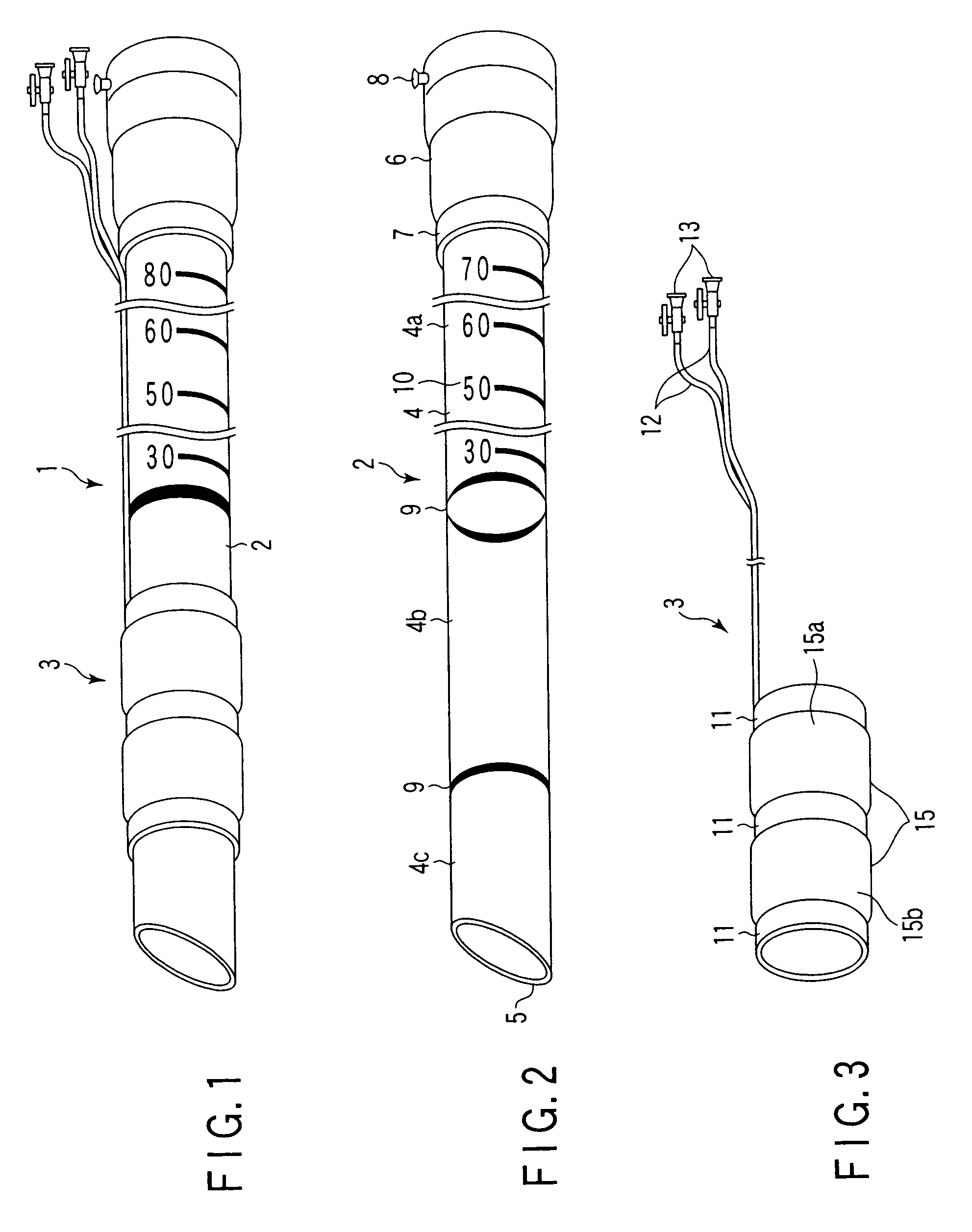
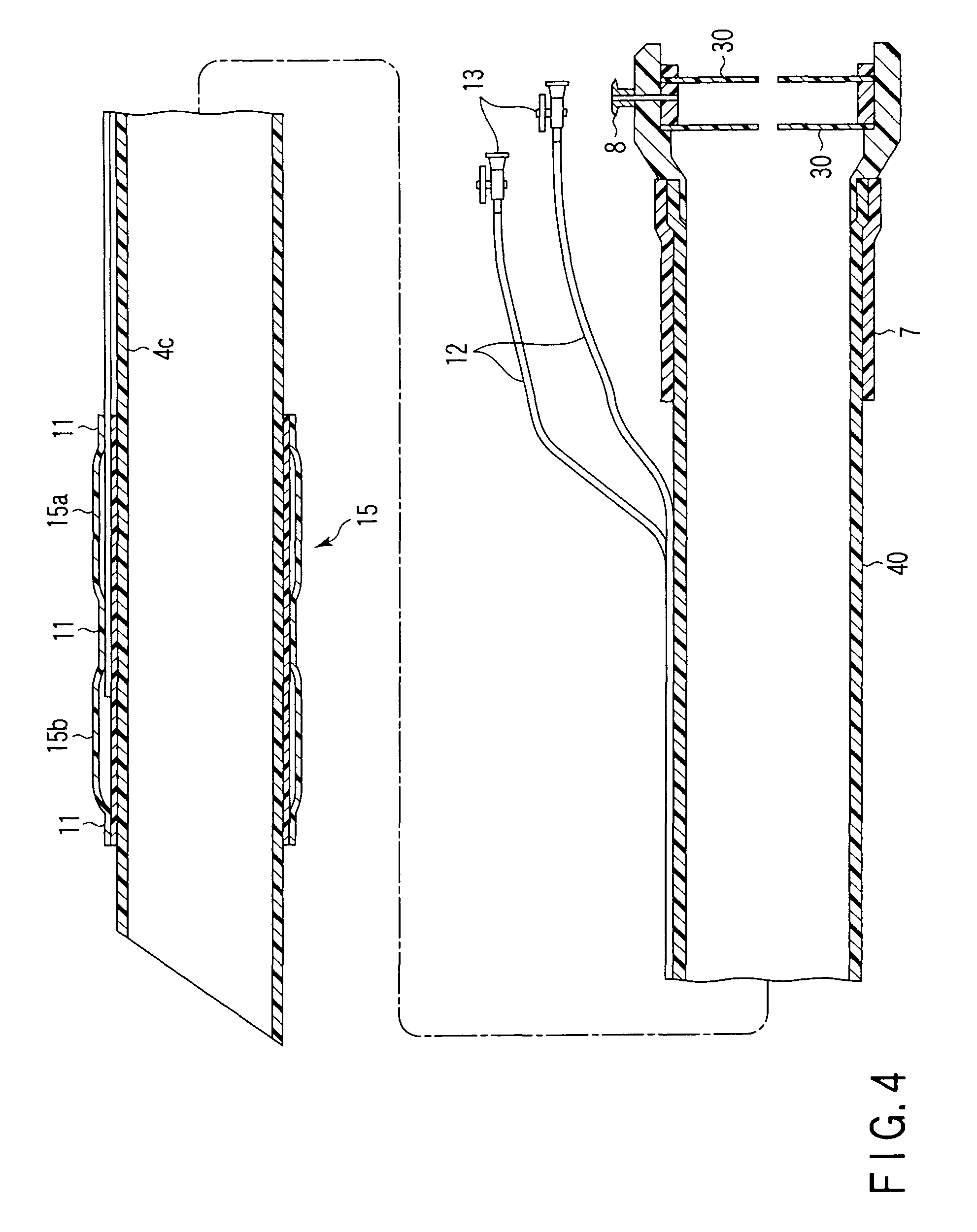
[0045]Referring to FIGS. 1 to 4, according to the present embodiment, a guide tube 1 guides an endoscope or a therapeutic device through the mouth and stomach wall into an abdominal cavity to conduct a diagnosis and a therapeutic treatment of the abdominal cavity. The guide tube 1 includes a flexible shaft section 2, which is thin and long and which can be inserted into a body cavity, and a balloon section 3 which is detachable from the periphery of the shaft section 2. The inner diameter of the balloon section 3 is formed so as to be slightly smaller than the outer diameter of the shaft section 2. The shaft section 2 is pressed into the balloon section 3, so that they can be fixed to each other. In the present embodiment, a distal end of the balloon section 3 is disposed at a distance of 20 mm from a distal end of the shaft section 2.

[0046]The shaft section 2 includes a tubular main body 4 and an operating handle 6. The tubular main bo...

third embodiment

[0065]FIGS. 17 to 24 show the present invention.

[0066]As shown in FIGS. 17 to 21, the guide tube 1 according to the present embodiment includes an outer-tube module 2a and an inner-tube module 2b which can be advanced or withdrawn in an inner bore of the outer-tube module 2a and which is inserted so as to hold airtightness.

[0067]The balloon section 3 is integrally connected to the outer-tube module 2a so that the distal end of the balloon section 3 is disposed at a distance of about 10 mm from a distal end of the outer-tube module 2a. An operating handle 6a in which the valve 30 (refer to FIG. 21) is arranged in the inner bore is disposed at the proximal end of the outer-tube module 2a. The overall length of the outer-tube module 2a is set to substantially 700 mm, the inner diameter thereof is set to about 18 mm, and the outer diameter thereof is set to about 20 mm.

[0068]The inner-tube module 2b has a central large-diameter inner bore, a forceps channel 22, and a small-diameter inne...

fourth embodiment

[0073]FIGS. 25 to 33 show the present invention.

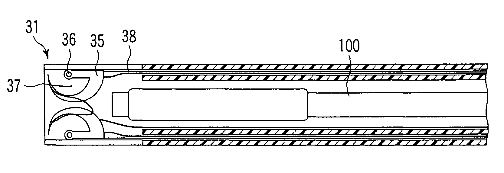
[0074]According to the present embodiment, as shown in FIG. 25, the endoscope guide tube 1, which is inserted through the mouth and stomach wall to conduct a diagnosis and a therapeutic treatment, has a flexible tubular main body 4. At least one slit 31 is formed at the distal end of the tubular main body 4. Preferably, two slits 31 facing each other in the radial direction are formed. In the inner bore at the distal end of the guide tube 1, both ends of a pair of shafts 36 facing in the transverse axis perpendicular to the longitudinal axis of the guide tube 1 are fixed to the tubular main body 4. The pair of shafts are arranged substantially in parallel to each other so as to face each other. A rotatable pulley 39 is rotatably provided for the periphery of each shaft 36. A curved needle 35 having a bent and sharp edge is attached to each pulley 39. The curved needle 35 has a concave hook 37 in the vicinity of the edge thereof. The ed...


PUM


Abstract

There is provided a flexible guide tube which guides an endoscope or a therapeutic device into an abdominal cavity through the mouth and stomach to conduct an observation or a therapeutic treatment in the abdominal cavity. The guide tube includes an insertion section which has a distal end, a peripheral section, and a central axis, and which is capable of being inserted into a body through the mouth, and two expandable and shrinkable balloons arranged in the vicinity of the distal end at a predetermined distance from each other in the axial direction on the periphery of the insertion section. The predetermined distance is preferably set to 3 to 8 mm, and the length of the insertion section is preferably set to about 600 to 1000 mm.

Description

CROSS-REFERENCE TO RELATED APPLICATIONS[0001]This application claims the benefit of U.S. Provisional Application No. 60 / 365,267, filed Mar. 18, 2002.BACKGROUND OF THE INVENTION[0002]The present invention relates to a guide tube and, more particularly, to a guide tube to guide an endoscope or a therapeutic device into a body.[0003]Hitherto, two methods have been generally used for a diagnosis and / or a therapeutic treatment using an endoscope. According to the first method, an endoscope is inserted through a bodily orifice, such as the mouth, anus, or urethra, to diagnose or therapeutically treat the alimentary canal, a digestive organ, or urinary organ. According to the second method, a perforation is formed in an abdominal wall on the outside of a body cavity and an endoscope is inserted through the perforation to conduct a diagnosis and a therapeutic treatment of an organ through an abdominal cavity. In the first method, since a perforation is not needed, the burden on the patient ...

Claims


Application Information

Patent Timeline
IPC IPC(8): A61B1/00G02B23/24A61B1/01A61B17/00A61B17/04A61B17/22A61B17/28A61B17/34A61B19/00A61M25/00A61M25/01
CPCA61B1/00082A61B1/00154A61B17/0057A61B17/0482A61B1/00135A61B2019/462A61B17/0401A61B2017/00278A61B2017/003A61B2017/00557A61B2017/00575A61B2017/0458A61B2017/0464A61B2017/0472A61B2017/0496A61B2017/22054A61B2017/22067A61B2017/22069A61B2017/2905A61B2019/461A61B2090/061A61B2090/062
Inventor ISHIKAWA, MASAHIROSUZUKI, KEITAKAWASHIMA, KOICHIYAMAMOTO, TETSUYAONUKI, YOSHIOSEKINE, RYUTAKALLOO, ANTHONY NICHOLASKANTSEVOY, SERGEY VENIAMINOVICH
Owner OLYMPUS CORP
Why Eureka
Try Eureka