Guidewire loaded stent for delivery through a catheter

a technology of stent and catheter, which is applied in the field of catheters and intravascular medical procedures, can solve problems such as problems with conventional stenting catheters

Inactive Publication Date: 2006-01-24
BACK BAY MEDICAL
View PDF28 Cites 332 Cited by
  • Summary
  • Abstract
  • Description
  • Claims
  • Application Information

AI Technical Summary

Benefits of technology

[0010]The guidewire body may be made of a conventional guidewire or it may also be formed from a hypotube having an initial diameter ranging from 0.007 to 0.014 in. Possible materials may include superelastic metals and alloys, e.g., Nitinol, or metals such as stainless steel, or non-metallic materials, e.g., polyimide. The hypotube may be further melted or ground down, depending upon the type of material used, into several sections of differing diameters. The distal end of the guidewire may be further tapered and is preferably rounded to aid in advancement through the vasculature. Radio-opaque coils may be placed over a portion of distal end to aid in radiographic visualization.

Problems solved by technology

Yet vasculature having a tortuous path and / or a small diameter, such as the intracranial vasculature, present problems for the conventional stenting catheter.

Method used


Image

  • Guidewire loaded stent for delivery through a catheter
  • Guidewire loaded stent for delivery through a catheter
  • Guidewire loaded stent for delivery through a catheter

Examples


Embodiment Construction

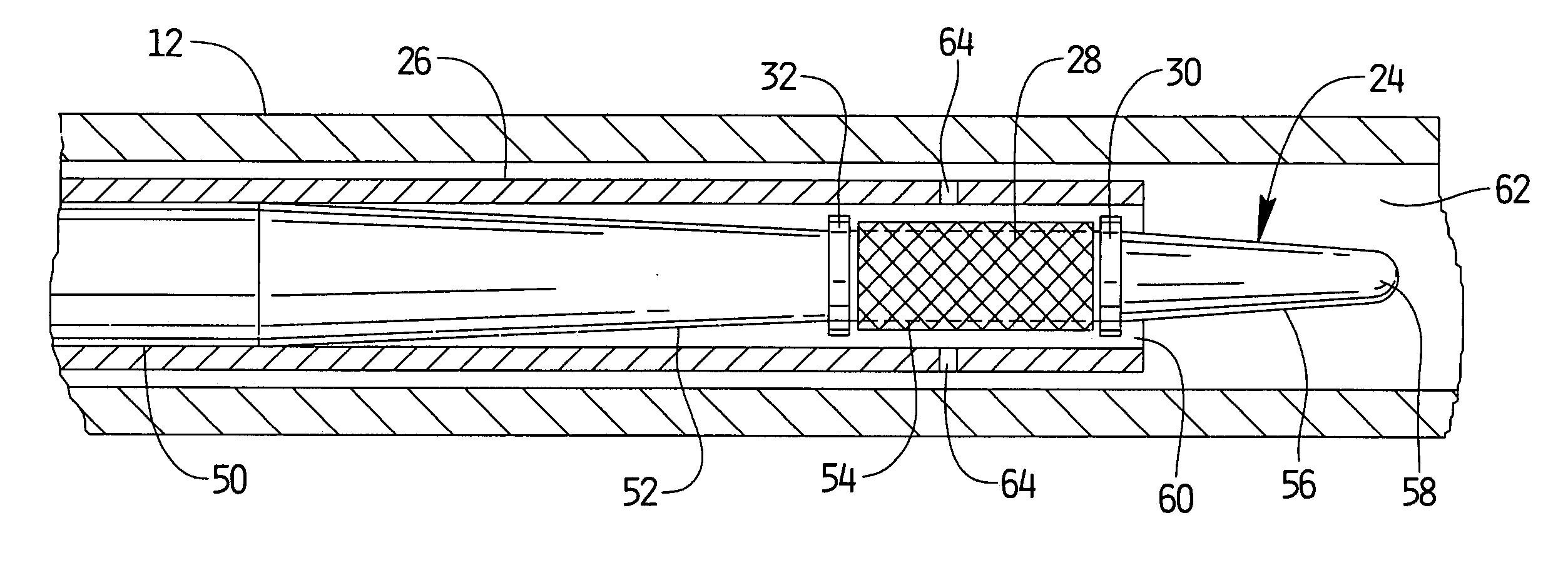
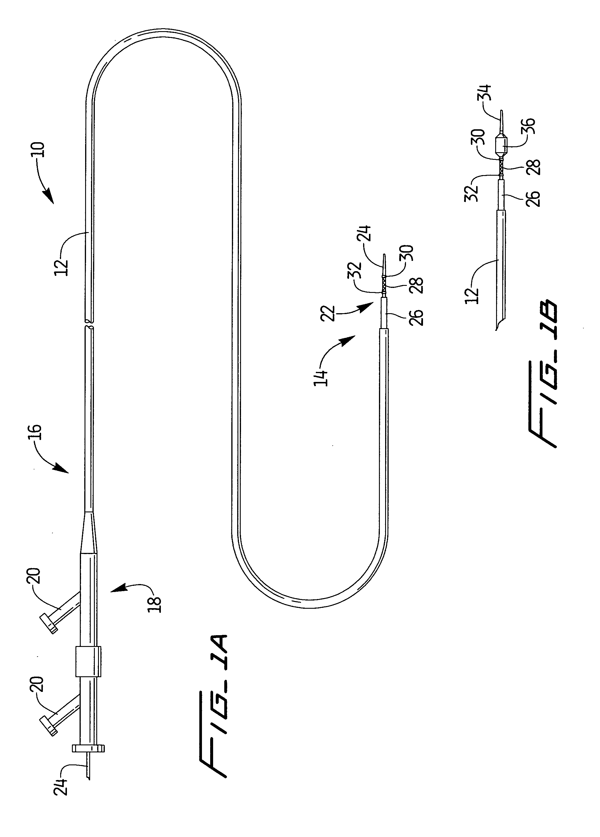
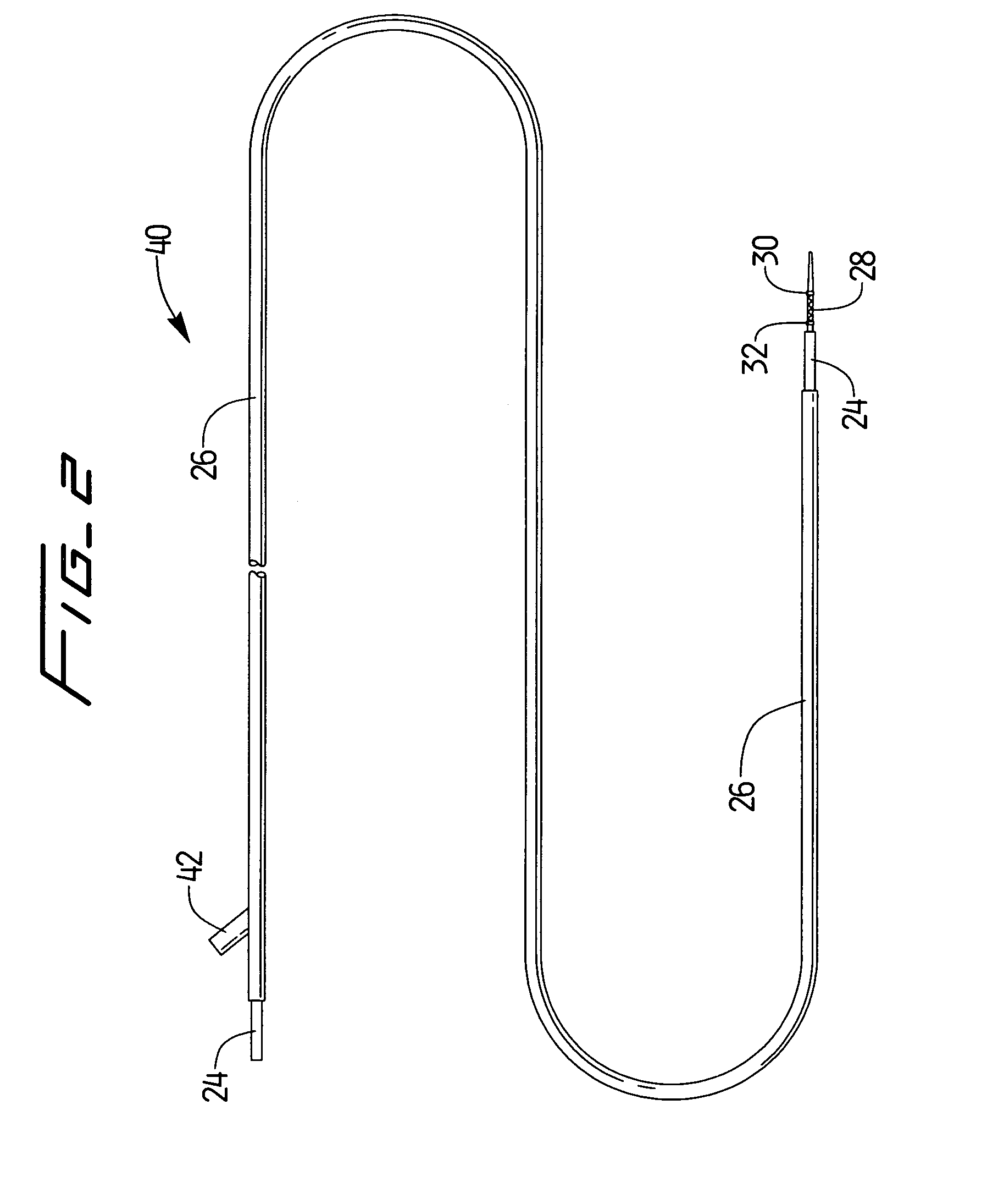
[0023]A stent delivery assembly having a small cross section and which is highly flexible is described herein. As shown in FIG. 1A, catheter assembly 10 is comprised of a conventional catheter body 12 having a distal end 14 and a proximal end 16. A fitting assembly 18 is attached to the proximal end 16 and may preferably have various attachments, e.g., Luer lock 20, to allow for access to catheter body 12 or the use of other instruments. Conventional catheter body 12 shows guidewire assembly 22 being slidably positioned therewithin. Assembly 22, which is described in further detail below, is shown in this variation as having a guidewire body 24 preferably covered at least in part by a retractable sheath 26. A radially expandable stent 28 is preferably disposed near the distal end of guidewire 24. Stent 28 may also be placed between an optional pair of radio-opaque marker bands 30, 32. One or both marker bands 30, 32 may be used or they may be left off the assembly entirely. The use ...


PUM


Abstract

A guidewire loaded stent for delivery through a catheter is described herein. The stent delivery assembly can deliver and place a stent within tortuous regions of the body which are accessible to guidewires but inaccessible to stenting catheters. The assembly comprises a guidewire covered in part by a retractable sheath and a radially expandable stent near or at the distal end of the guidewire. The whole assembly is advanced through conventional catheters or it may be used alone. In either case, when the stent is adjacent to a treatment site within the body, the sheath is retracted proximally to expose the stent for radial expansion into contact with the vessel wall. Radio-opaque marker bands are optionally located on either side or both sides of the stent on the guidewire body to aid in visual placement. The assembly can optionally include an expandable balloon on the guidewire for different treatment modalities.

Description

TECHNICAL FIELD OF THE INVENTION[0001]The present invention relates generally to catheters and intravascular medical procedures. More particularly, it relates to methods and apparatus for delivering a stent through a catheter by way of a guidewire delivery device.BACKGROUND ART OF THE INVENTION[0002]Intravascular stents are well known in the medical arts for the treatment of vascular stenoses. Stents are prostheses which are generally tubular and which expand radially in a vessel or lumen to maintain its patency. For deployment within the body's vascular system, most stents are mounted onto a balloon angioplasty catheter for deployment by balloon expansion at the site of a dilated stenosis or an aneurysm. Self-expanding stents, which typically expand from a compressed delivery position to its original diameter when released from the delivery device, generally exert a radial force on the constricted portion of the body lumen to re-establish patency. One common self-expanding stent is...

Claims


Application Information

Patent Timeline
Patent Type & Authority Patents(United States)
IPC IPC(8): A61F2/06A61F2/84A61M25/09
CPCA61F2/95A61F2/958A61F2/966A61M25/09A61M2025/09183A61M2025/09008A61F2002/9583
Inventor HEBERT, STEPHENLEVINE, MARC-ALAN
Owner BACK BAY MEDICAL
Why Eureka
Try Eureka