Apparatus and method for removing a molded article from a mold

a technology of injection molding and removing a mold, which is applied in the field of methods and apparatus for injection molding of preforms, can solve the problems of inability to maintain proper seal with the closure, the mold is closed and clamped, and the sealing surface portion is irregular, so as to shorten the manufacturing time of blow molding containers, reduce cycle time and cost

Inactive Publication Date: 2006-01-24
HUSKY INJECTION MOLDING SYST LTD
View PDF22 Cites 37 Cited by
  • Summary
  • Abstract
  • Description
  • Claims
  • Application Information

AI Technical Summary

Benefits of technology

[0024]It is an object of the present invention to provide cooling method and apparatus for efficiently cooling molded plastic preforms.
[0025]According to a first aspect of the present invention, structure and / or steps are provided for ejecting a molded plastic preform from a molding structure. Lifting structure is provided with: (i) a first portion configured to contact the molded plastic preform along a line substantially parallel to a lifting direction; (ii) a second portion configured to contact an end of the molded plastic preform along a line substantially perpendicular to the lifting direction. Since the preform is lifted by its end, the preform does not have to be solidified at its interior, thus reducing cycle time; and (iii) a third portion disposed on an opposite side of the second portion from the first portion, the third portion having a tapered surface having an angle of less than ninety degrees with respect to the second portion.

Problems solved by technology

The time needed to injection-mold the preform is typically limited by the time needed to cool and solidify injected polymer material sufficiently to permit removal of the part from the mold without causing deformation or distortion.
If the polymer material has not sufficiently solidified throughout the neck-finish wall cross-section, the neck-finish will not have sufficient strength to transmit the force and thus can deform and distort during removal causing the sealing surface portion to become irregular and incapable of maintaining proper seal with the closure.
In addition to the distortion problem described above, another problem with known mold designs is where the neck ring halves do not seal against the core when they are closed (assembled), and the mold is then closed and clamped.
However, this design is not optimal since, if there is a gap between these two cylindrical surfaces greater than about 0.005 inch, the risk of plastic leaking through this gap during injection is significant.
Unfortunately, molds wear as they are used, and eventually a design like this leaks.
However, this design was not optimal because the preform still had neck-ring distortions when it was stripped from the core.
However, this design suffered from two disadvantages.
First the small area of contact between the neck ring and the top sealing surface still required substantial cooling time to prevent neck ring distortions.
Second, this design had the cylindrical neck ring mating surfaces which allowed for leakage of the molten plastic.

Method used


Image

  • Apparatus and method for removing a molded article from a mold
  • Apparatus and method for removing a molded article from a mold
  • Apparatus and method for removing a molded article from a mold

Examples


Embodiment Construction

1. Introduction

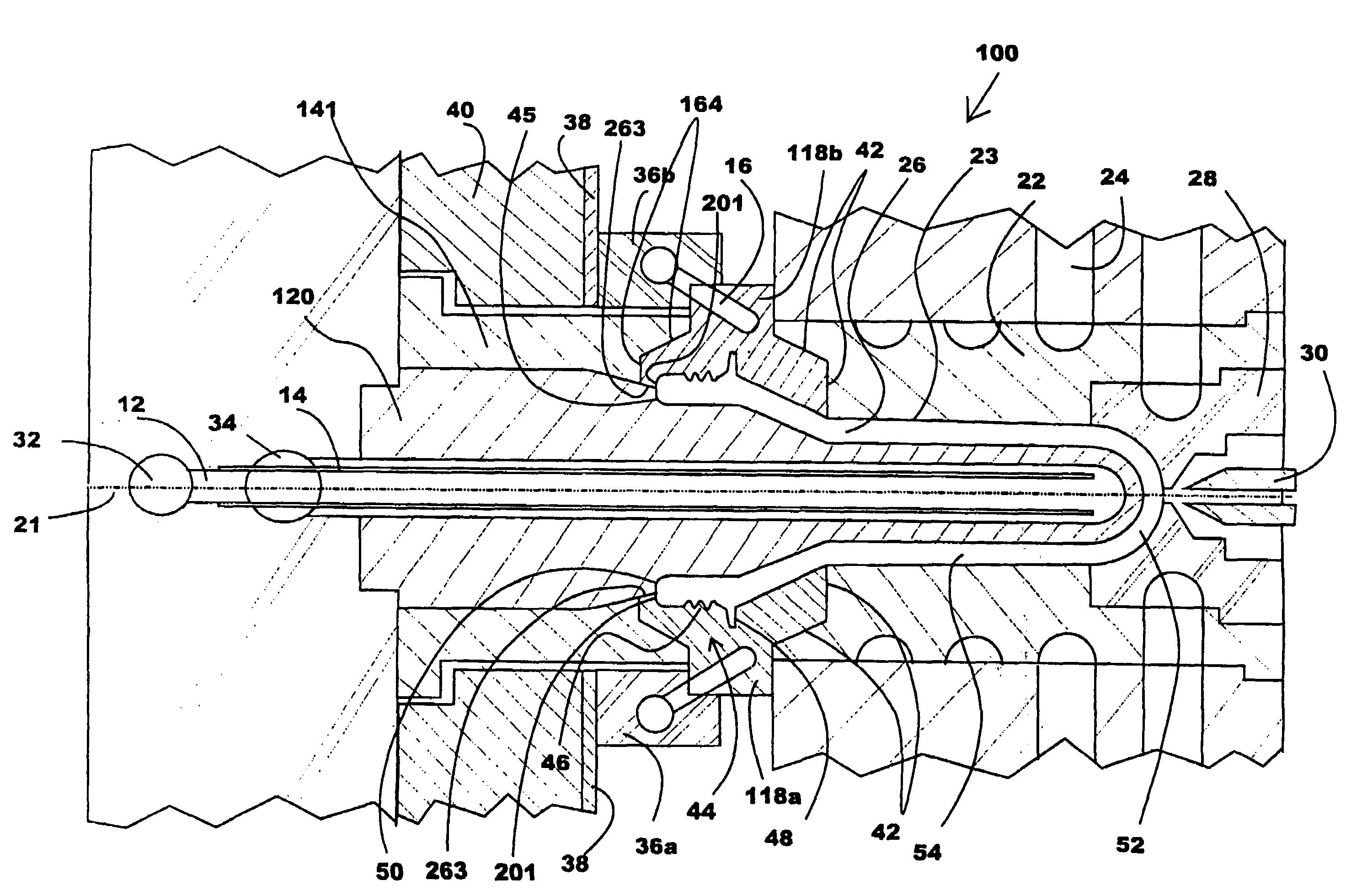
[0041]The present invention will now be described with respect to several embodiments in which a neck ring applies a compressive force to the open, circular end of an injection-molded plastic preform before the preform is completely solidified, thus reducing cycle time, and in which conical neck ring mating surfaces are used to prevent leakage. However, the present invention will find applicability in many molding technologies beyond injected-molded plastic preforms, such as the molding of containers, pails, trays, paint cans, tote boxes, and similar products, or other molded products possibly with non-circular cross-sectional shapes, etc.

[0042]In brief, the preferred embodiments of the present invention will redistribute the forces acting on the neck-finish during preform removal. By reconfiguring the neck-ring or neck split components to bear against not only the handling ring portion and the threaded portion, but also the sealing surface portion, the preferred embo...


PUM

PropertyMeasurementUnit
acute angleaaaaaaaaaa
angleaaaaaaaaaa
timeaaaaaaaaaa

Abstract

Injection molding method and apparatus for ejecting a molded plastic article from a mold. A lifting structure and / or step is provided with a lifting portion which is configured to contact substantially one half of an end of the molded plastic article along a line substantially perpendicular to the lifting direction. Since the molded plastic article is lifted by its end, the article does not have to be solidified at its interior, thus allowing earlier removal of the article from the mold, reducing cycle time. A tapered surface forms an acute angle with respect to the lifting portion to form a tight seal with the mold, preventing leakage. Preferably, the neck ring engages only an outer circumferential portion of the molded plastic article during a majority of a mold opening stroke.

Description

BACKGROUND OF THE INVENTION[0001]1. Field of the Invention[0002]The present invention relates to method and apparatus for injection molding of preforms so that their subsequent reheating and blow-molding into containers is simplified. In particular, the present invention relates to a method and apparatus for providing an improved neck-ring or neck split components of an injection mold that allows for an earlier ejection or removal of the preform from the injection mold, thus reducing time needed to manufacture the preform. The method and apparatus are particularly well suited for thermoplastic polyester polymer materials such as polyethylene terephthalate.[0003]2. Related Art[0004]Well known by those skilled in the art, the preform is a tube with a generally hollow circular cross-sectional configuration having a body portion, a closed end portion with a generally hemispherical configuration, and an open end. About the open end and superimposed between the open end and the body porti...

Claims


Application Information

Patent Timeline
Patent Type & Authority Patents(United States)
IPC IPC(8): B29C45/44B29C45/73
CPCB29C45/44B29K2105/253B29C2045/445B29C45/73B29C45/40
Inventor MILLER, WILLIAM E.DONG, LINGXINFAVOT, FRANKMARSHALLPAEGEL, WALTERYAKIMISHYN, RANDY
Owner HUSKY INJECTION MOLDING SYST LTD
Why Eureka
Try Eureka