
Electric motor

a technology of electric motors and motor housings, applied in the direction of mechanical energy handling, magnetic circuit shapes/forms/construction, shielding from electromagnetic fields, etc., can solve the problem of considerable eddy current loss in steel housings, and achieve the effect of occupying a large space and adding cos

Inactive Publication Date: 2006-01-24
ATLAS COPCO AIRPOWER NV
View PDF2 Cites 10 Cited by
  • Summary
  • Abstract
  • Description
  • Claims
  • Application Information

AI Technical Summary

Benefits of technology

[0016]The ring avoids leakage of the magnetic flux towards the outside, for instance towards the outer housing of the motor. Leakage flux may cause considerable eddy current loss in a steel housing.
[0017]The motor will be somewhat larger, but the integrated filter inductances can use the same cooling system as the rest of the motor. There is no need for a separate cooling system which would take much space and add cost.

Problems solved by technology

Leakage flux may cause considerable eddy current loss in a steel housing.

Method used


Image

  • Electric motor
  • Electric motor
  • Electric motor

Examples


Embodiment Construction

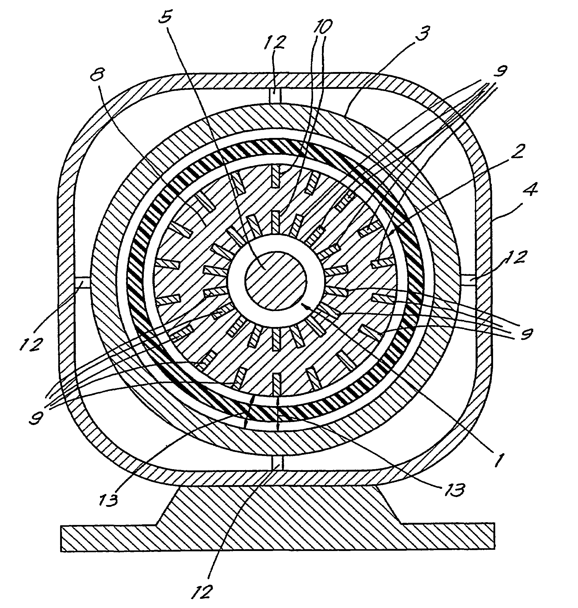
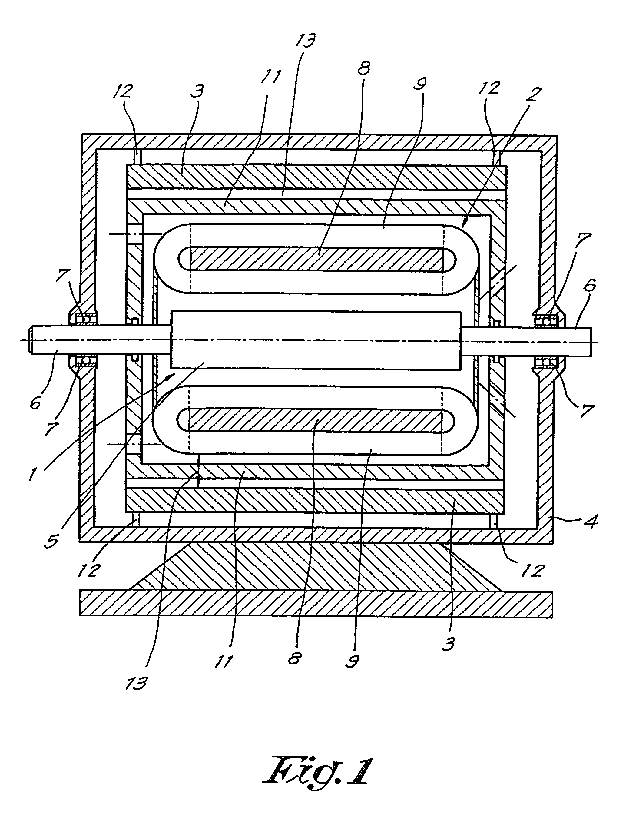
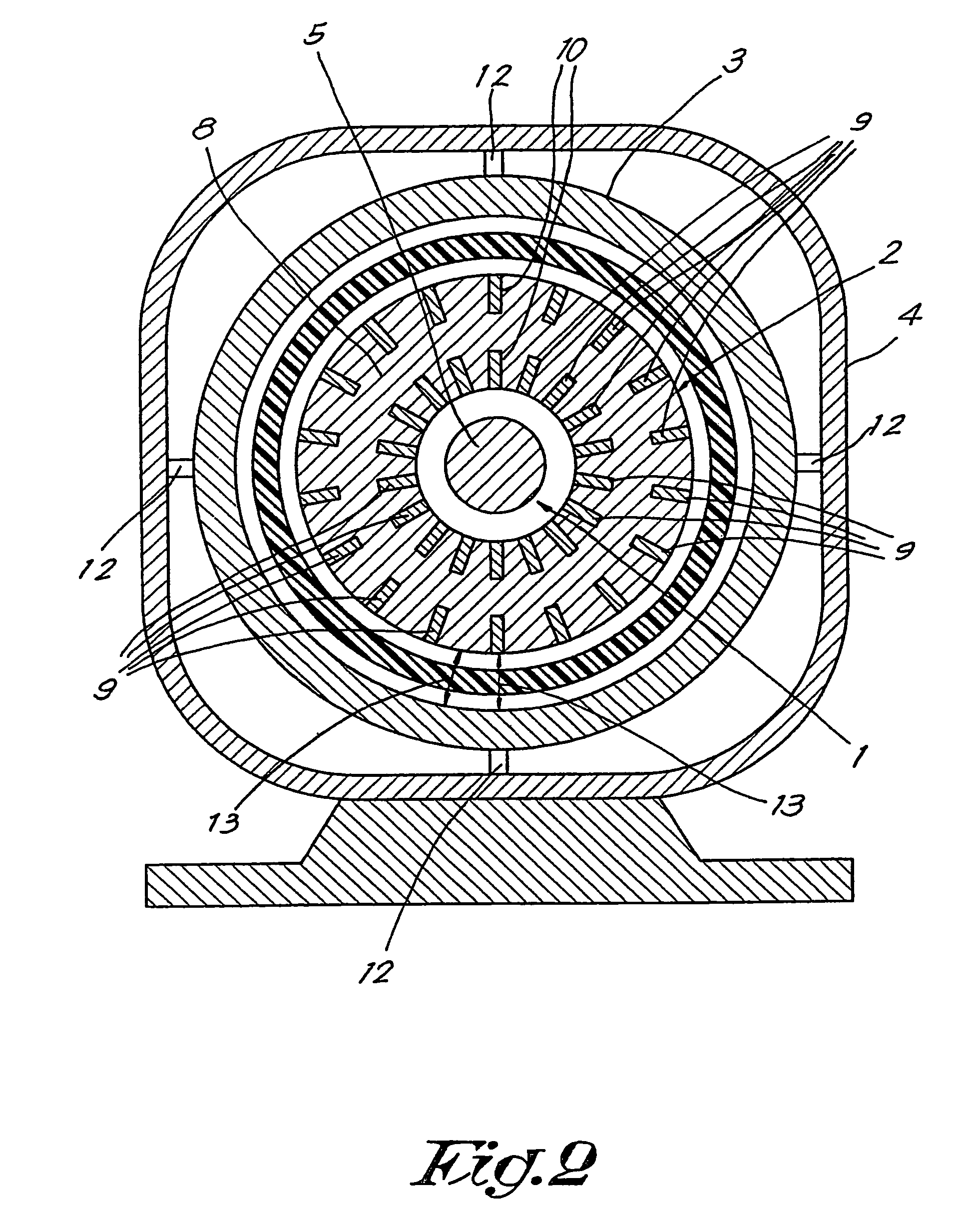
[0025]The motor shown in FIG. 1 is a three-phase permanent magnet synchronous A.C electric motor, comprising essentially a rotor 1, a stator 2 surrounding the rotor 1, an inductance controlling ring 3 surrounding the stator 2, and an outer housing 4.

[0026]The rotor 1 consists of a permanent magnet part 5 mounted on an axis 6, the end of which is supported in bearings 7 in the outer housing 4.

[0027]The stator 2 has a tubular core 8 and is provided with a number of stator windings 9 extending like rings around the core wall, with half-turns at the outside of the core 8 and half-turns at the inside of the core 8. The half-turns of the windings 9 are sunken in slots 10 in the core 8, although in another embodiment the windings 9 are not in slots.

[0028]For containing cooling oil, the stator 2 is also surrounded by an internal housing 11 in non-magnetic material, for example plastics.

[0029]The inductance controlling ring 3 is situated inside the motor, between the outer housing 4 and this...


PUM


Abstract

The invention relates to an electric motor, in particular for high speed operation, comprising a motor housing (4); inside the housing (4), a stator (2) having a core (8) and windings (9) toroidally wound on the core (8); and a rotor (1) inside the stator (2). The motor comprises an inductance controlling ring (3) in soft-magnetic material around the stator core (8), increasing for each phase the leakage inductance and forming for each phase an integrated filter inducatnce (L1, L2, L3) outside the core (8) of the stator (2) but still inside the motor housing (4).

Description

BACKGROUND OF THE INVENTION[0001]1. Field of the Invention[0002]The present invention relates to an electric motor, in particular for high speed operation, comprising a housing; inside this housing, a stator having a core and windings toroidally wound on the core, with half-turns at the inside of the core and half-turns at the outside of the core; and inside the stator, a rotor.[0003]2. Description of Related Art[0004]In high speed motors the distribution of losses differs considerably from the distribution of losses in standard speed motors.[0005]The speed of these high speed motors is commonly frequency controlled by an inverter. Due to harmonics coming from this inverter, the eddy current losses can easily become the dominant loss.[0006]As these eddy current losses increase as the square of the design speed for the same frame size of the motor, these losses can be high compared with standard speed motors.[0007]Moreover, as these losses have a tendency to be concentrated to the ro...

Claims


Application Information

Patent Timeline
Patent Type & Authority Patents(United States)
IPC IPC(8): H02K11/00H02K1/06H02K9/19H02K11/01H02K21/14
CPCH02K11/0005H02K11/01
Inventor NILSON, THORD AGNE GUSTAF
Owner ATLAS COPCO AIRPOWER NV
Learn More