Piezoelectric resonant filter and duplexer

a technology of resonant filter and duplexer, which is applied in the direction of impedence network, electrical apparatus, and electro-electrostrictive/magnetostrictive devices, etc., can solve the problems of increasing the width of the pass band of the filter, and affecting the performance of the filter. , to achieve the effect of suppressing the reduction of the pass band width and preventing the variation of the pass band in accordance with temperature chang

Active Publication Date: 2006-01-24
SNAPTRACK
View PDF19 Cites 135 Cited by
  • Summary
  • Abstract
  • Description
  • Claims
  • Application Information

AI Technical Summary

Benefits of technology

[0044]The invention is developed in consideration of the problems and an object of the invention is to provide a piezoelectric resonant filter in which drawbacks caused by variation in the pass band of the filter in accordance with temperature change can be prevented while reduction in width of the pass band can be suppressed, and a duplexer including such piezoelectric resonant filters.
[0051]In the first duplexer according to the invention, the rate of frequency change in accordance with temperature change at a frequency which is one nearer to the second pass band out of a frequency exhibiting the first low frequency side attenuation extremum and a frequency exhibiting the first high frequency side attenuation extremum is lower than the rate of frequency change in accordance with temperature change at the other frequency.
[0054]In the second duplexer according to the invention, the rate of frequency change in accordance with temperature change at a frequency which is one nearer to the first pass band out of a frequency exhibiting the second low frequency side attenuation extremum and a frequency exhibiting the second high frequency side attenuation extremum is lower than the rate of frequency change in accordance with temperature change at the other frequency.
[0057]In the third duplexer according to the invention, the rate of frequency change in accordance with temperature change at a frequency which is one nearer to the second pass band out of a frequency exhibiting the first low frequency side attenuation extremum and a frequency exhibiting the first high frequency side attenuation extremum is lower than the rate of frequency change in accordance with temperature change at the other frequency.
[0058]In the third duplexer according to the invention, the rate of frequency change in accordance with temperature change at a frequency which is one nearer to the first pass band out of a frequency exhibiting the second low frequency side attenuation extremum and a frequency exhibiting the second high frequency side attenuation extremum is lower than the rate of frequency change in accordance with temperature change at the other frequency.

Problems solved by technology

In the present situation, however, many technical problems still remain in order to adapt the surface acoustic wave filter to the frequency that will be worked as a higher frequency in the mobile communication apparatus in the future.
Accordingly, in the filter using thin-film piezoelectric resonators as the series and parallel resonators, there is a problem that the pass band of the filter varies according to temperature change when the resonant frequency of each thin-film piezoelectric resonator varies according to temperature change.
In a duplexer, when the pass band of the transmission filter or the pass band of the reception filter varies according to temperature change, the following problem occurs.
In this case, particularly variation in the frequency of the transmission filter exhibiting the high frequency side attenuation extremum and variation in the frequency of the reception filter exhibiting the low frequency side attenuation extremum become issues.
This is because variations in these frequencies cause lowering of performance of the duplexer for separating the transmission signal and the reception signal from each other.
In this case, reduction in the pass band width of the filter due to the provision of the temperature compensating film cannot be suppressed.
Accordingly, also in this case, reduction in the pass bandwidth of the filter caused by the provision of the temperature compensating film cannot be suppressed.
For this reason, in this case, reduction in the pass band width of the filter caused by the provision of the dielectric layer cannot be suppressed.
For this reason, even in the case where silicon oxide is used as the material of the film, the thickness of the film cannot be optimized to bring the temperature coefficient of the resonant frequency of the resonator close to zero.
For this reason, even in the case where SiO2 is used as the material of the thin film, the thickness of the thin film cannot be optimized to bring the temperature coefficient of the resonant frequency of the resonator close to zero.

Method used


Image

  • Piezoelectric resonant filter and duplexer
  • Piezoelectric resonant filter and duplexer
  • Piezoelectric resonant filter and duplexer

Examples


Embodiment Construction

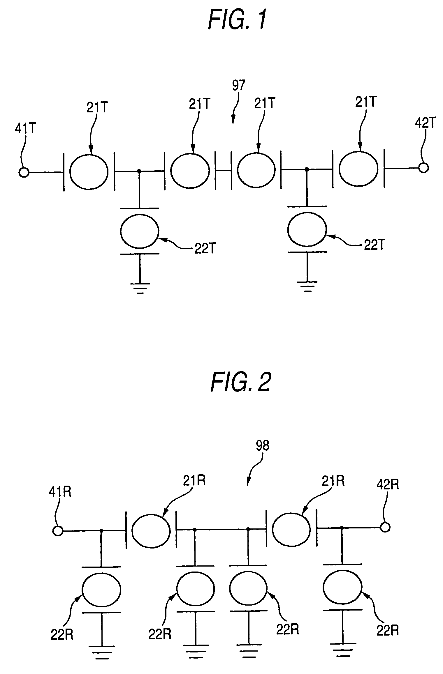
[0062]FIG. 1 is a circuit diagram showing an example of circuit configuration of a transmission filter in a duplexer according to an embodiment of the invention;

[0063]FIG. 2 is a circuit diagram showing an example of circuit configuration of a reception filter in the duplexer according to the embodiment of the invention;

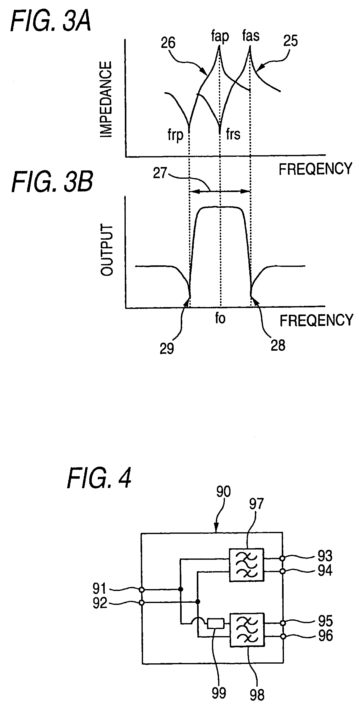
[0064]FIGS. 3A and 3B are views for explaining frequency characteristics of piezoelectric resonant filters in the embodiment of the invention;

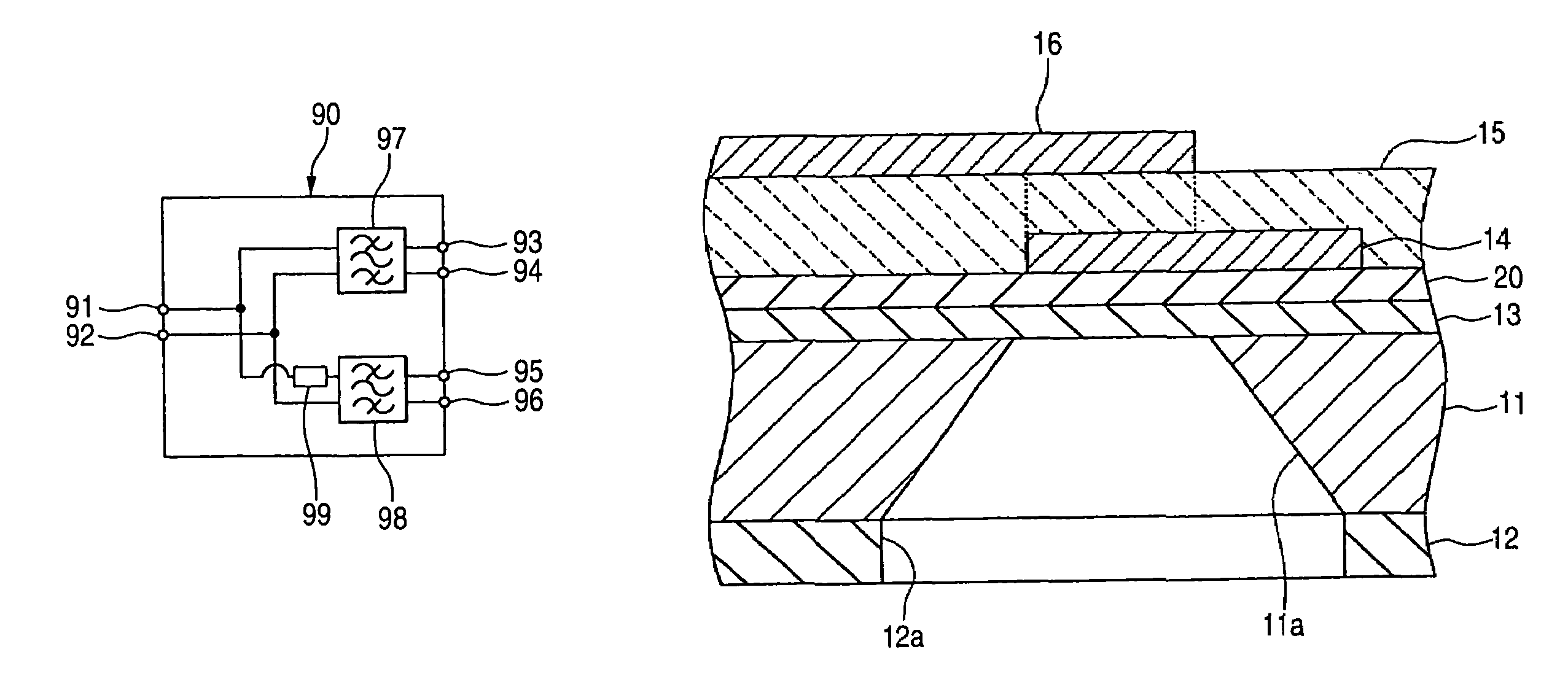
[0065]FIG. 4 is a circuit diagram of the duplexer according to the embodiment of the invention;

[0066]FIG. 5 is a characteristic graph showing an example of frequency characteristic of the duplexer according to the embodiment of the invention;

[0067]FIG. 6 is a graph for explaining temperature characteristic of resonant frequency of each thin-film piezoelectric resonator in the embodiment of the invention;

[0068]FIG. 7 is a sectional view showing an example of configuration of each thin-film piezoelectric resonator in the embodime...


PUM


Abstract

A piezoelectric resonant filter includes a group of series resonators and a group of parallel resonators for forming a ladder-type filter circuit. Each of the resonators has a piezoelectric thin film having piezoelectric characteristic, and lower and upper electrodes disposed on opposite surfaces of the piezoelectric thin film for applying an excitation voltage to the piezoelectric thin film. The group of the parallel resonators exhibits a low frequency side attenuation extremum in the filter whereas the group of the series resonators exhibits a high frequency side attenuation extremum in the filter. At least one of the group of the series resonators and the group of the parallel resonators has a temperature compensating layer for bringing the temperature coefficient of the resonant frequency close to zero.

Description

BACKGROUND OF THE INVENTION[0001]The present invention relates to a piezoelectric resonant filter containing thin-film piezoelectric resonators, and a duplexer containing such piezoelectric resonant filters.[0002]In mobile communication apparatuses such as cellular phones that have been spread remarkably in recent years, both reduction in size and increase in working frequency have advanced year by year. For this reason, both reduction in size and increase in workable frequency have been required of electronic components used in the mobile communication apparatuses.[0003]Some mobile communication apparatus has a duplexer for performing switching between a transmission signal path and a reception signal path so that one antenna can be used for both transmission and reception. The duplexer has a transmission filter for passing a transmission signal but cutting off a reception signal, and a reception filter for passing the reception signal but cutting off the transmission signal.[0004]...

Claims


Application Information

Patent Timeline
Patent Type & Authority Patents(United States)
IPC IPC(8): H03H9/54H03H9/70H03H3/04H03H9/58H03H9/02H03H9/17H03H9/24H03H9/60
CPCH03H3/04H03H9/02102H03H9/02149H03H9/175H03H9/605H03H9/706H03H9/174H03H2003/0407H03H9/24
Inventor KOMURO, EIJUSAITOU, HISATOSHINOGUCHI, TAKAOABE, HIDENORI
Owner SNAPTRACK
Why Eureka
Try Eureka