Zoom lens and photographing apparatus having the same

a technology of zoom lens and photographing apparatus, which is applied in the field of zoom lens, can solve the problems of large size of the whole apparatus, complicated moving mechanism of the movable lens unit, and large image shake, so as to improve the optical performance of the image stabilizing operation, correct the decentering aberration, and the effect of increasing the size of the whole mechanism

Inactive Publication Date: 2006-01-24
CANON KK
View PDF35 Cites 24 Cited by
  • Summary
  • Abstract
  • Description
  • Claims
  • Application Information

AI Technical Summary

Benefits of technology

[0084]According to the embodiment of the invention, the zoom lens further has the following characteristic features, thereby obtaining the more advantageous effects.
[0085]First, the conditions under which the image stabilizing lens unit is made small in size and light in weight and is made optimum in terms of optical performance will be described in the following. The amount of decentering E4s of the image-stabilizing lens unit required for obtaining a predetermined amount of image-shake correction ΔYp on an image plane is expressed by the following equation (m) on the basis of the equation (b) with R=0, ω=0 and αk′=1.E4s=−ΔYp / {2(ΔE)}  (m)
[0086]Since the primary original point shift (ΔE) is expressed by the equation (h), the amount of decentering E4s required for obtaining a necessary amount of image-shake correction ΔYp is defined by using a converted inclination angle of incidence α and a converted inclination angle of exit α′ of an on-axial marginal ray on and from the image-stabilizing lens unit. Accordingly, the zoom lens is made to satisfy the following condition (1):α′−α<−0.45  (1)
[0087]If the condition (1) is not satisfied, the increase of the amount of decentering E4s causes the amount of movement of the image-stabilizing lens unit to increase rapidly, and, in addition, the effective diameter of the image-stabilizing lens unit is increased in consideration of the decentering, so that the required driving force increases rapidly, resulting in an increase in size of the whole mechanism. Further, in association with the increase of the amount of decentering E4s, the occurrence of decentering aberration becomes large, so that the optical performance during the image stabilizing operation deteriorates.
[0088]In addition, the image-stabilizing lens unit may be composed of one negative lens. However, since, from the viewpoint of the equations (c) to (g), in order to correct decentering aberrations caused by the image-stabilizing lens unit, it is necessary to appropriately control the various shared values of aberration coefficients of the image-stabilizing lens unit, it is preferable that the image-stabilizing lens unit is composed of at least one positive lens and at least one negative lens. By this arrangement, it becomes easy to control the various shared values of aberration coefficients of the image-stabilizing lens unit. Thus, it becomes easy to correct decentering aberrations, so that the various decentering aberrations, such as decentering coma and decentering curvature of field, can be prevented from easily occurring during the image stabilizing operation. It is more preferable that the image-stabilizing lens unit consists of one positive lens and one negative lens or consists of one positive lens and two negative lenses.
[0089]Further, from the viewpoint of the equation (l), in order to correct decentering chromatic aberrations caused by the image-stabilizing lens unit, it is necessary to appropriately control the various shared values of chromatic aberration coefficients of the image-stabilizing lens unit.

Problems solved by technology

In addition, it has become a large problem to suppress an image shake caused by the vibration of a photographing system which has a long focal length or the vibration of hands holding the photographing system.
In general, the method of obtaining a stationary image by disposing an image stabilizing optical system in front of a photographing system and driving and controlling a movable lens unit that is a part of the image stabilizing optical system to prevent the shaking of a photographed image causes such a problem that the whole apparatus becomes large in size and a moving mechanism for moving the movable lens unit becomes complicated.
In an optical system in which the image stabilization is performed by means of a variable angle prism, a problem arises in that the amount of occurrence of decentering lateral chromatic aberration becomes large, in particular, on the telephoto side during the image stabilization.
On the other hand, in an optical system in which the image stabilization is performed by causing a lens unit that is a part of a photographing system to decenter in a direction perpendicular to the optical axis, although there is such an advantage that it is unnecessary to provide a specific optical system used for the image stabilization, a problem arises in that a space is required for the lens unit to be moved and the amount of occurrence of decentering aberration during the image stabilization becomes large.
Hei 7-92431, the front lens subunit of positive refractive power serving as an image-stabilizing lens unit has a relatively large effective diameter, and, as a result, there is a tendency for the image-stabilizing lens unit to become large and heavy to increase the size of a driving mechanism for the image-stabilizing lens unit.
Hei 10-90601, since the fourth lens unit is a lens unit arranged to move in the optical axis direction during the variation of magnification, there is a tendency for a driving control mechanism for the fourth lens unit to become complicated.

Method used


Image

  • Zoom lens and photographing apparatus having the same
  • Zoom lens and photographing apparatus having the same
  • Zoom lens and photographing apparatus having the same

Examples


numerical example 1

[0131]

f = 9.99978  Fno = 1:1.8-3.3  2ω = 57.6°-1.4°r1 = 262.527d1 = 5.50n1 = 1.83932ν1 = 37.2r2 = 148.600d2 = 0.20r3 = 146.720d3 = 19.47n2 = 1.43496ν2 = 95.1r4 = 1711.919d4 = 11.35r5 = 446.535d5 = 12.04n3 = 1.43496ν3 = 95.1r6 = −528.168d6 = 0.07r7 = −522.929d7 = 5.00n4 = 1.77621ν4 = 49.6r8 = −7601.809d8 = 0.30r9 = 189.702d9 = 18.57n5 = 1.43496ν5 = 95.1r10 = −890.210d10 = 0.30r11 = 150.001d11 = 11.18n6 = 1.49845ν6 = 81.6r12 = 393.239d12 = Variabler13 = 521.146d13 = 2.00n7 = 1.77621ν7 = 49.6r14 = 53.105d14 = 4.73r15 = −148.563d15 = 1.80n8 = 1.77621ν8 = 49.6r16 = 51.373d16 = 6.72r17 = −66.261d17 = 1.80n9 = 1.79025ν9 = 50.0r18 = 47.388d18 = 7.80n10 = 1.93306ν10 = 21.3r19 = −366.607d19 = Variabler20 = 633.050d20 = 6.36n11 = 1.43985ν11 = 95.0r21 = −113.045d21 = 0.30r22 = 201.150d22 = 2.50n12 = 1.65223ν12 = 33.8r23 = 53.110d23 = 13.60n13 = 1.59143ν13 = 61.2r24 = −155.230d24 = 0.20r25 = 131.701d25 = 13.00n14 = 1.62032ν14 = 63.4r26 = −75.433d26 = 2.50n15 = 1.85501ν15 = 23.9r27 = −155.034d27 ...

numerical example 2

[0132]

f = 10.00000  Fno = 1:1.8-3.1  2ω = 57.6°-1.4°r1 = 262.527d1 = 5.50n1 = 1.83932ν1 = 37.2r2 = 148.600d2 = 0.20r3 = 146.720d3 = 19.47n2 = 1.43496ν2 = 95.1r4 = 1711.919d4 = 11.35r5 = 446.535d5 = 12.04n3 = 1.43496ν3 = 95.1r6 = −528.168d6 = 0.07r7 = −522.929d7 = 5.00n4 = 1.77621ν4 = 49.6r8 = −7601.809d8 = 0.30r9 = 189.702d9 = 18.57n5 = 1.43496ν5 = 95.1r10 = −890.210d10 = 0.30r11 = 150.001d11 = 11.18n6 = 1.49845ν6 = 81.6r12 = 393.239d12 = Variabler13 = 521.146d13 = 2.00n7 = 1.77621ν7 = 49.6r14 = 53.105d14 = 4.73r15 = −148.563d15 = 1.80n8 = 1.77621ν8 = 49.6r16 = 51.373d16 = 6.72r17 = −66.261d17 = 1.80n9 = 1.79025ν9 = 50.0r18 = 47.388d18 = 7.80n10 = 1.93306ν10 = 21.3r19 = −366.607d19 = Variabler20 = 633.050d20 = 6.36n11 = 1.43985ν11 = 95.0r21 = −113.045d21 = 0.30r22 = 201.150d22 = 2.50n12 = 1.65223ν12 = 33.8r23 = 53.110d23 = 13.60n13 = 1.59143ν13 = 61.2r24 = −155.230d24 = 0.20r25 = 131.701d25 = 13.00n14 = 1.62032ν14 = 63.4r26 = −75.433d26 = 2.50n15 = 1.85501ν15 = 23.9r27 = −155.034d27...


PUM


Abstract

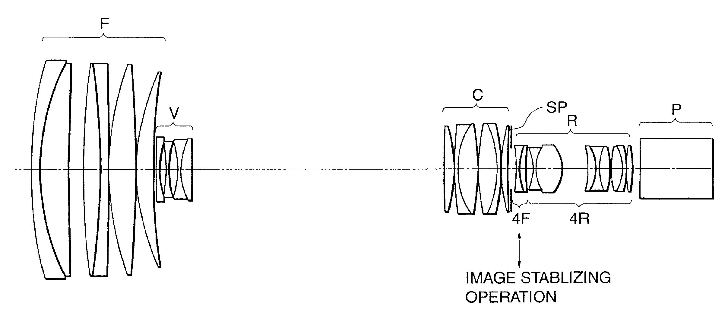
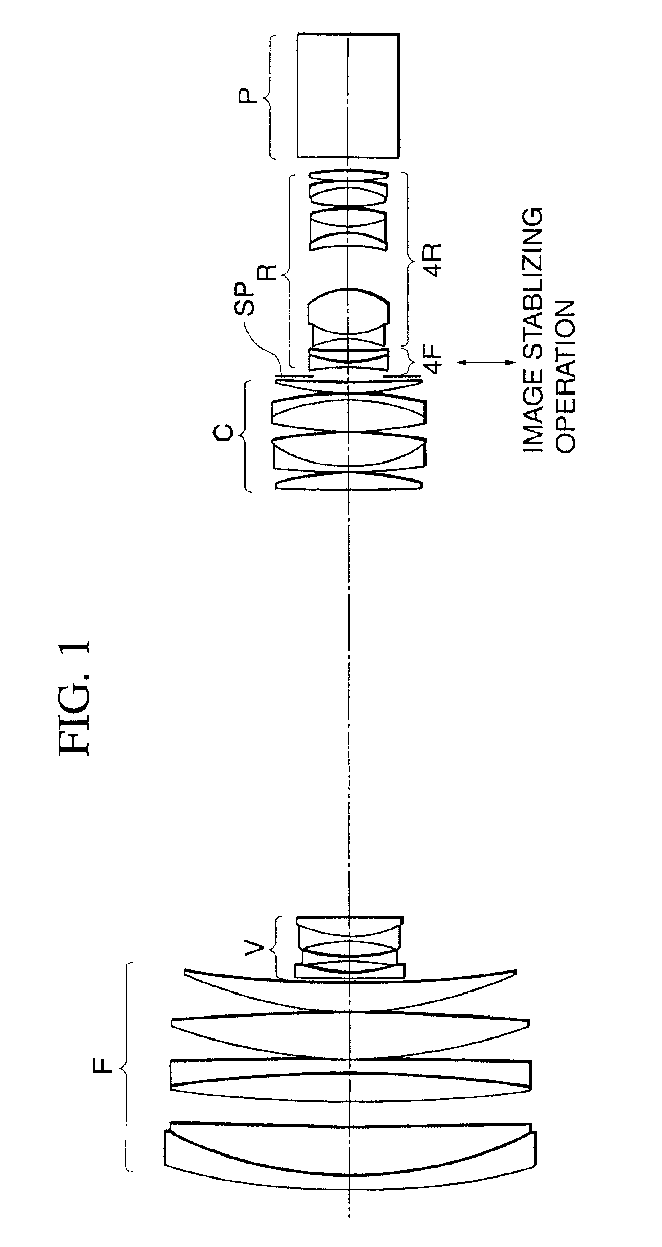
A zoom lens includes, in order from an object side to an image side, a first lens unit of positive refractive power, a second lens unit of negative refractive power arranged to move during variation of magnification, a third lens unit arranged to compensate for shift of an image plane due to the variation of magnification, and a fourth lens unit of positive refractive power, wherein the fourth lens unit has a first lens subunit of negative refractive power, and an image is displaced by moving the first lens subunit in such a way as to have a component perpendicular to an optical axis of the zoom lens.

Description

BACKGROUND OF THE INVENTION[0001]1. Field of the Invention[0002]The present invention relates to a zoom lens having an image stabilizing function, and, more particularly, to a zoom lens having an image stabilizing function, which is suited for a television camera, a photographic camera, a video camera or the like, and which has high optical performance over the entire range of variable magnification even during an image stabilizing operation in which a lens unit that is a part of the lens system is made to move in a direction perpendicular to the optical axis so as to correct an image shake caused by the vibration of the zoom lens for the purpose of obtaining a stationary image, with the construction of the zoom lens, such as the refractive power arrangement of the whole zoom lens and the arrangement of the moving lens units for the variation of magnification, appropriately set. Further, the present invention relates to a photographing apparatus having such a zoom lens.[0003]2. Desc...

Claims


Application Information

Patent Timeline
Patent Type & Authority Patents(United States)
IPC IPC(8): G02B15/163G02B27/64G02B15/10G02B15/20G02B15/16G02B15/173G03B5/00
CPCG02B27/646G02B15/173G02B15/144113
Inventor NURISHI, RYUJI
Owner CANON KK
Why Eureka
Try Eureka