Method and apparatus for adjusting packet transmission volume from a source

a packet transmission and source technology, applied in the field of methods, can solve the problems of queues in the network that might have overflown, cannot be directly detected by tcp, and cannot know when the network is congested, and achieve the effect of increasing utilization

Inactive Publication Date: 2006-01-24
RPX CLEARINGHOUSE
View PDF29 Cites 123 Cited by
  • Summary
  • Abstract
  • Description
  • Claims
  • Application Information

AI Technical Summary

Benefits of technology

[0018]Effectively, by communicating a desired volume value to the transmitter, in response to a receiver volume value produced by the receiver and a difference between a target departure volume and an estimate of arrival volume of data at a queue through which data passes from the transmitter to the receiver, the volume of packets communicated by the transmitter continually changes, depending on both the status of the queue and the status of the receiver. Consequently, the volume of packets received at the queue is varied with each time interval. A queue controlled in such a manner is less likely to overflow or be under-utilized. Effectively, the volume of packets which a transmitter communicates through the queue is varied, as r

Problems solved by technology

The TCP flow control mechanism is meant to reduce the packet volume when the network becomes congested, but TCP has no direct way of knowing when the network is congested.
It can only indirectly detect congestion by keeping track of how many packets are lost.
Packet loss indicates that some queue in the network might have overflowed.
In a high-latency network environment, the window flow control mechanism of TCP may not be very effective because it relies on packet loss to signal congestion, instead of preventing congestion and buffer overflow.
The basic problem is that TCP does not communicate directly with the network elements to determine optimal or assigned traffic volumes for respective elements.
By the time the transmitter starts decreasing its volume because of packet loss, the network has already become overly congested.
This problem exists because the design of TCP only considers the flow c

Method used


Image

  • Method and apparatus for adjusting packet transmission volume from a source
  • Method and apparatus for adjusting packet transmission volume from a source
  • Method and apparatus for adjusting packet transmission volume from a source

Examples


Embodiment Construction

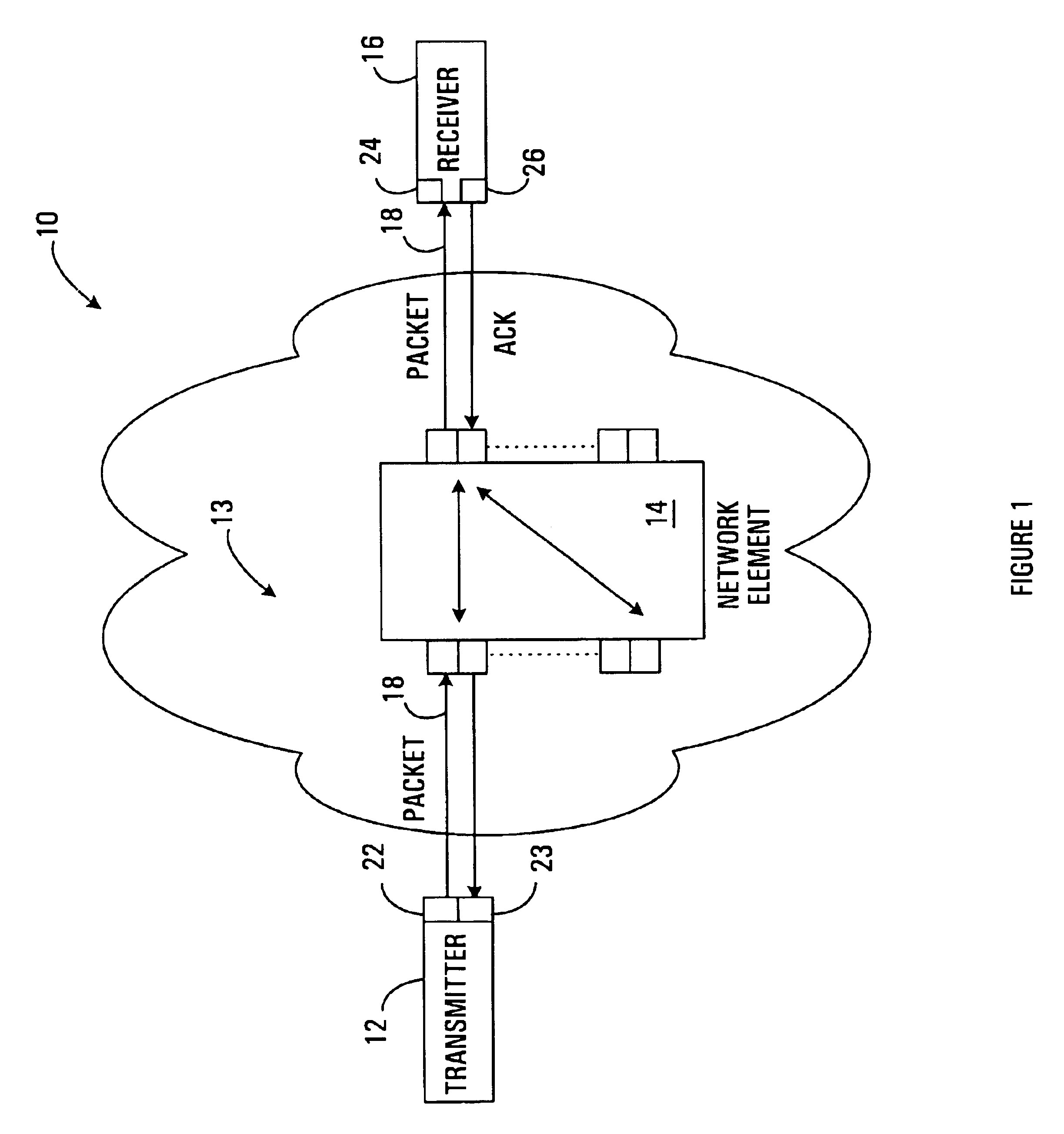
[0027]As shown generally at 10 in FIG. 1, a network according to a first embodiment of the invention includes a first data transmitter 12, a network element 14 and a first data receiver 16. In general, the transmitter 12 transmits data in a forward direction to the network element 14 which, in turn, transmits the data to the receiver 16. It will be appreciated that there may be a plurality of network elements between a plurality of transmitters and a plurality of receivers, however, for simplicity only one of each is shown.

[0028]In this embodiment, the data transmitted by the transmitter 12 is transmitted as “forward” packets 18 which are communicated in a forward direction i.e. from the transmitter to the receiver 16. In this specification, the term “packet” is applied broadly, and contemplates any quantum of data, such as a block, a frame, a datagram, a cell, a word, a byte, or a bit, for example. In general, a transmitter 12-receiver 16 pair that exchanges packets via one or more...


PUM


Abstract

A method and apparatus are provided for adjusting the volume of data communicated between a transmitter and a receiver on a network, in a time interval. The method involves producing a desired volume value in response to a volume value specified by the receiver and a difference between a target departure volume and an estimate of arrival volume of data at a queue through which data passes from the transmitter to the receiver, and communicating the desired volume value to the transmitter in response to an acknowledgement signal produced by the receiver.

Description

BACKGROUND OF THE INVENTION[0001]1. Field of the Invention[0002]The present invention relates to communication over a packet network, and more particularly to adjusting the number of packets which are communicated between a transmitter and a receiver on the network in a time interval to reduce queue congestion.[0003]2. Description of Related Art[0004]With the proliferation of internet and data communications, communication networks are being used to carry an increasing amount of traffic. At the same time, user expectations for network speed and reliability are also increasing.[0005]In a packet network such as the Internet for example, packets of information are conveyed between a packet transmitter and a packet receiver. The transmitter may be any device that transmits data on the network and the receiver may be any device that receives data from the network. Typically, a receiver will send an acknowledgement signal to a transmitter of a packet to indicate that a packet has been rec...

Claims


Application Information

Patent Timeline
IPC IPC(8): H04J1/16
CPCH04L47/10H04L47/12H04L47/30H04L47/27H04L47/29H04L47/193
Inventor AWEYA, JAMESMONTUNO, DELFIN Y.QUELLETTE, MICHEL
Owner RPX CLEARINGHOUSE
Why Eureka
Try Eureka