X-ray computed tomographic imaging apparatus

a computed tomography and x-ray technology, applied in tomography, instruments, nuclear engineering, etc., can solve the problems of affecting the image quality of the peripheral portions of an mpr image, and the volume ratio of the data omission portion to the reconstruction area fov is very limited, so as to prevent data omission and unnecessary x-ray irradiation

Inactive Publication Date: 2006-01-24
LUCENT TECH INC +1
View PDF9 Cites 66 Cited by
  • Summary
  • Abstract
  • Description
  • Claims
  • Application Information

AI Technical Summary

Benefits of technology

[0012]It is an object of the present invention to prevent both data omission and unnecessary X-ray irradiation in multi-slice CT or cone-beam CT.

Problems solved by technology

This results in unnecessary areas (shaded portions) irradiated with X-rays in spite of the fact that no image data is reconstructed outside the reconstruction area FOV.
The following problem arises in a cone-beam CT apparatus.
Although the data is acquired in a view at an opposite direction, this data omission affects the image quality of the peripheral portions of an MPR image.
In practice, however, in single-slice CT, the volume ratio of the data omission portion to the reconstruction area FOV is very much limited, and hence no significant problem arises.
As shown in FIG. 6, however, when the reconstruction area FOV is set to a small radius, areas outside the reconstruction area FOV are excessively irradiated with X-rays, resulting in an increase in X-ray dose.

Method used


Image

  • X-ray computed tomographic imaging apparatus
  • X-ray computed tomographic imaging apparatus
  • X-ray computed tomographic imaging apparatus

Examples


first embodiment

(First Embodiment)

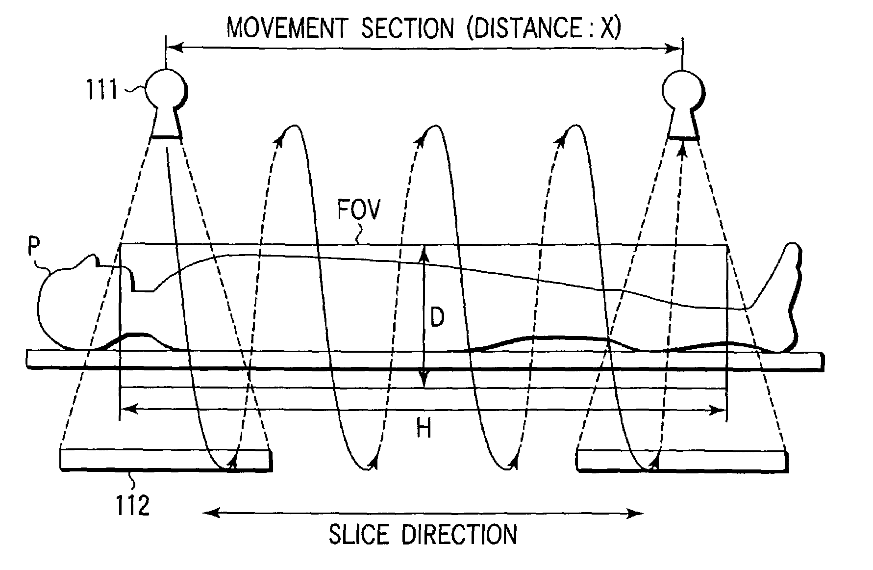
[0039]FIG. 7 shows an arrangement of an X-ray CT apparatus according to the first embodiment. A gantry 11 has a hollow portion. To scan, an object P to be examined placed on a top 113 of a bed is inserted into the hollow portion. The bed has an electric motor for moving the top 113 upon reception of driving power from a table top driver 131.

[0040]The gantry 11 has an X-ray tube 111 and X-ray detector 112. The X-ray tube 111 generates X-rays upon reception of a high voltage from a high voltage generator 111a. The X-ray detector 112 has a plurality of detection elements constituted by, for example, scintillators and photodiodes. The plurality of detection elements are arranged two-dimensionally in the channel and slice directions. For example, M detection elements are arrayed in a line in the channel direction, and N array segments of such detection elements are arrayed along the slice direction.

[0041]The X-ray tube 111 and X-ray detector 112 are rotatably supported ...

second embodiment

(Second Embodiment)

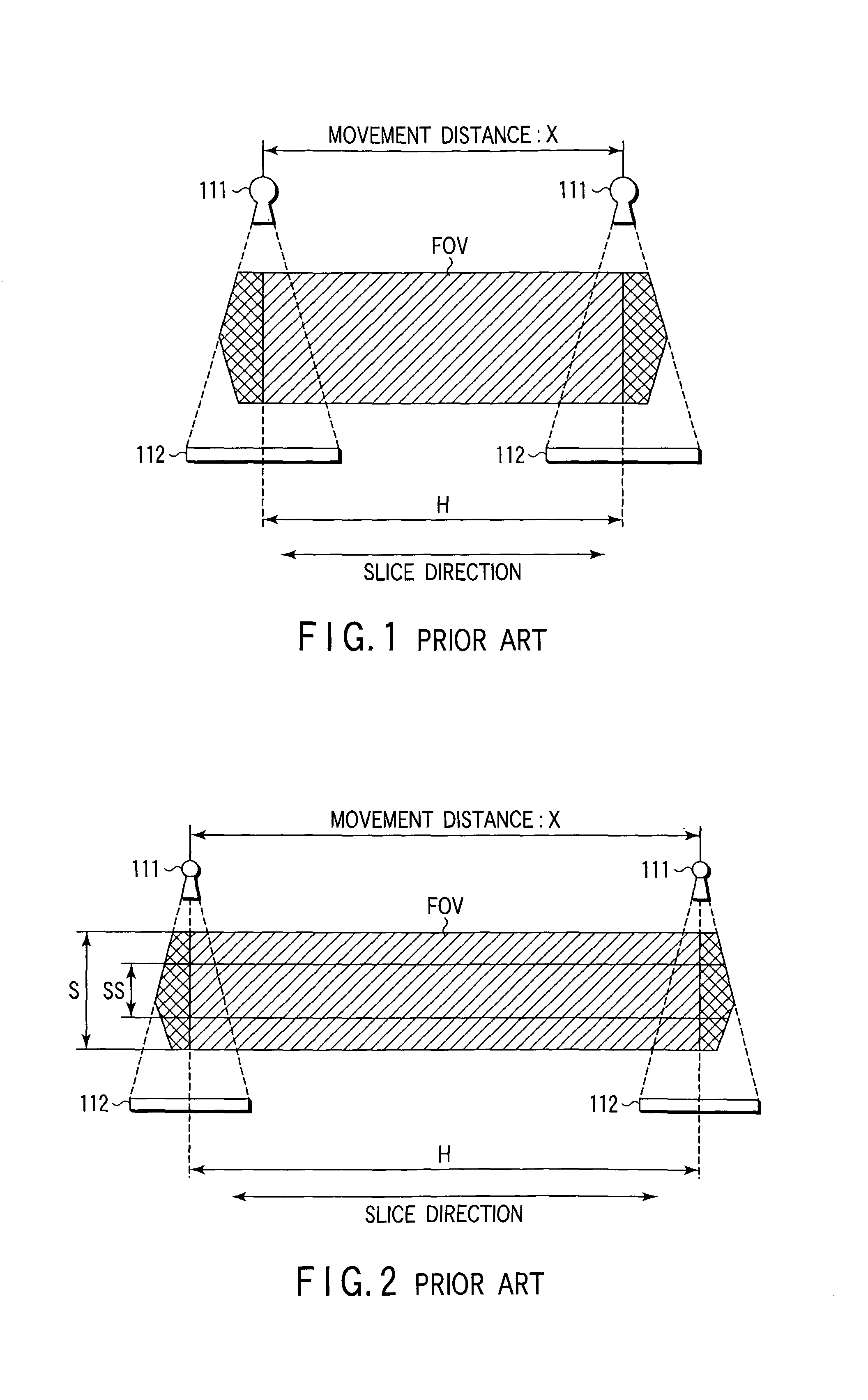
[0061]The first embodiment described above relates to the technique of preventing data omission and unnecessary X-ray generation in a helical scan in multi-slice or cone-beam CT. The second embodiment relates to a technique of preventing data omission and unnecessary X-ray generation in a conventional scan in multi-slice or cone-beam CT.

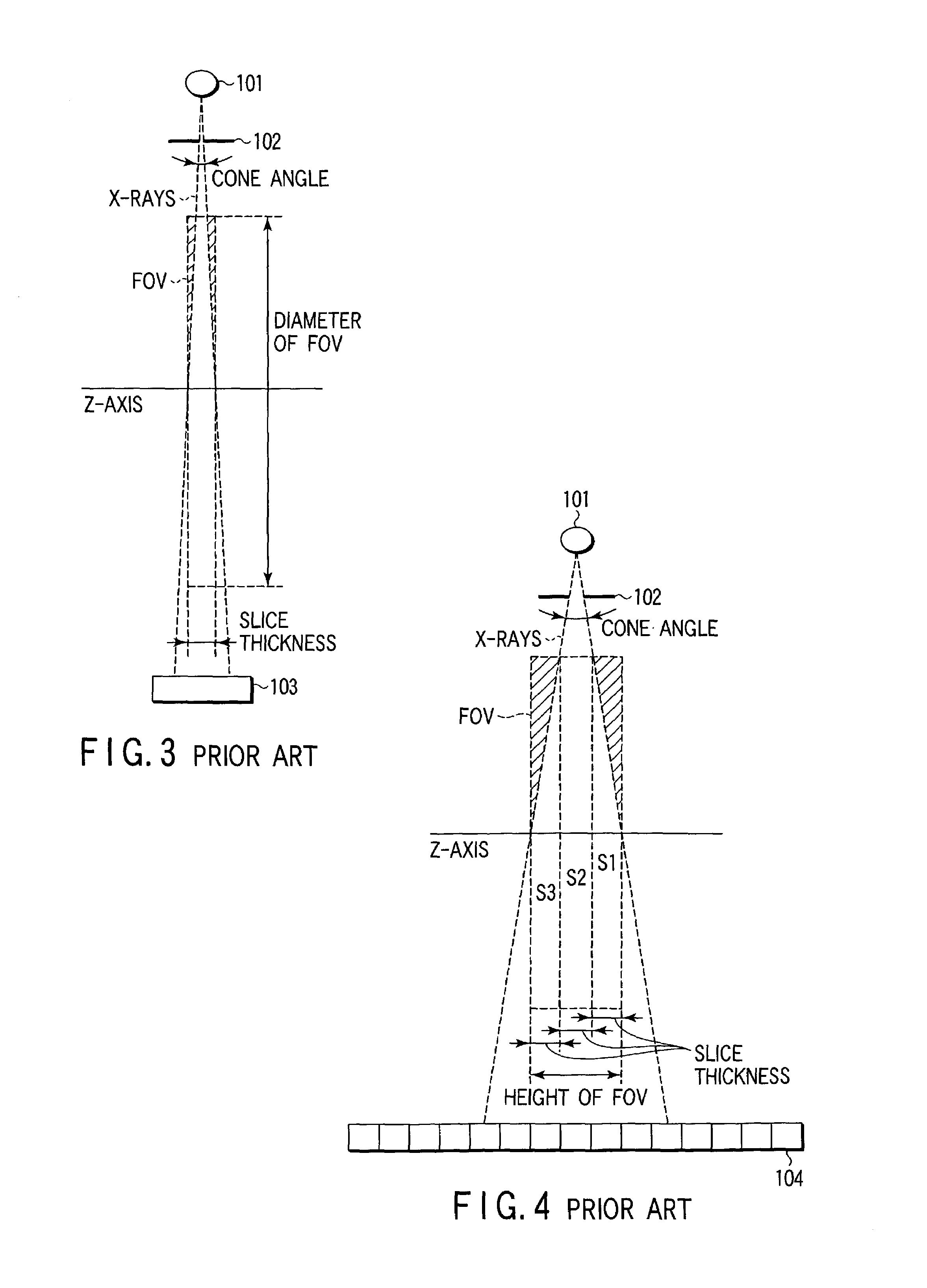
[0062]A conventional scan is a scan that is performed to acquire data while an X-ray tube is fixed relative to an object to be examined. For example, as shown in FIG. 14, many arrays (e.g., 600 arrays) of X-ray detectors DET are arranged in the body axis direction to oppose an X-ray tube 111 with collimator CM and exemplary beams BM1 and BM2. Multi-slice data are acquired by rotating these X-ray detectors around a object P to be examined while a wide-angle cone beam (with large cone and fan angles) is radiated from the X-ray tube 111. Assume that the cone angle is fixed, and a reconstruction area P1 with a large radius is to be sca...


PUM


Abstract

An X-ray computed tomography apparatus includes a cone beam X-ray tube, an X-ray detector, a rotating mechanism for supporting the X-ray tube and X-ray detector, a moving mechanism for moving the object in the slice direction, a control unit for controlling the rotating mechanism and moving mechanism to execute helical scan operation and move relative to the object, an input device for setting a substantially cylindrical reconstruction area, and an image reconstructing unit for reconstructing image data within the set reconstruction area based on the output of the detector. The apparatus also includes a movement distance determining unit for determining the movement distance of the X-ray tube and X-ray detector relative to the object on the basis of the radius of the set reconstruction area as well as its height.

Description

CROSS-REFERENCE TO RELATED APPLICATIONS[0001]This application is based upon and claims the benefit of priority from the prior Japanese Patent Applications No. 2001-241755, filed Aug. 9, 2001; and No. 2001-361346, filed Nov. 27, 2001, the entire contents of both of which are incorporated herein by reference.BACKGROUND OF THE INVENTION[0002]1. Field of the Invention[0003]The present invention relates to a multi-slice or cone-beam X-ray computed tomography apparatus.[0004]2. Description of the Related Art[0005]A cone-beam CT apparatus has a larger number of detector arrays and a wider X-ray divergence angle in the slice direction than a multi-slice CT apparatus. Typically, the number of detector arrays mounted in a multi-slice CT apparatus is, for example, 4, 8, or 16, whereas that in a cone-beam CT apparatus reaches as many as 256 or 512.[0006]Such a cone-beam CT apparatus can perform “helical scan” like a single-slice CT apparatus or multi-slice CT apparatus. Helical scan is a techni...

Claims


Application Information

Patent Timeline
Patent Type & Authority Patents(United States)
IPC IPC(8): A61B6/03G06T11/00
CPCA61B6/032G06T11/006A61B6/5241A61B6/027
Inventor SUGIHARA, NAOKISOEJIMA, NOBUKATSU
Owner LUCENT TECH INC
Why Eureka
Try Eureka