
System for manipulating noise in digital images

a digital image and noise technology, applied in image data processing, image enhancement, instruments, etc., can solve the problems of large-band noise, inclusion of such noise, and often unwanted excessive noise, and achieve the effect of preserving fine image detail and overall sharpness

Inactive Publication Date: 2006-01-24
ADOBE SYST INC
View PDF14 Cites 103 Cited by
  • Summary
  • Abstract
  • Description
  • Claims
  • Application Information

AI Technical Summary

Problems solved by technology

Many images include such noise as a result of the processes used to acquire the image from a real-world source or introduced during subsequent processing or reproduction.
For example, excessive noise is often unwanted, in that it may detract from perfect reproduction or interfere with certain subsequent technical processes.
Generally, broad-band noise alters all pixels of the image.
Examples of such noise include film grain, noise originating in the light-sensitive component (e.g. CCD array) of digital still or video cameras, and analog static and in general noise caused by electrical fluctuations in the components of an electronic image recording or reproduction system.
This could be for aesthetic reasons or as in the field of digital image and video compression prior to storage or transmission, image noise of almost any sort reduces the efficacy of such compression systems, because it represents spurious “detail” that the compression algorithm attempts to reproduce.
Almost always, the exact noise pattern of an image—as opposed to the general characteristics of the noise—is not of interest, so encoding this information wastes valuable storage space or transmission time.
Some filters do not operate well on color images or on image sequences.
For example, an algorithm not specifically designed to process image sequences may be temporally unstable with the result that changing artifacts are introduced on a frame-to-frame basis causing a popping or strobing effect which is known as image “chatter”.
All noise reduction systems degrade the source image to some degree during processing, taking the form of a loss of fine image detail or an overall blurring of the image.
This tradeoff is unavoidable as fine detail is difficult to distinguish from noise, however a good algorithm will minimize the amount of degradation induced at a given level of noise reduction.
Thus, reducing noise while preserving image sharpness and detail is a difficult problem.
Current systems do not operate effectively both across the color channels (if present) and between the frames (if present) of an image sequence.
Even for still or monochrome images, existing algorithms represent an often poor solution for broad-band noise, resulting in either little noise reduction or excessive blurring.
Hence, the noise reduction techniques employed in practice on broad-band noise are often limited to mild Gaussian blurs or the application of a median filter.
On the other hand, adding noise to an existing image is a simpler problem.
The scene is stored as a digital image and contains film grain noise as a result of its chemical photography origin The image of the synthetic object does not, so if these two images are composited naively the lack of film grain where the computer-generated object is visible detracts from the realism of the resulting scene.
For example, multiple photographic elements recorded under identical conditions will have mis-matched grain noise if they appear scaled differently the final composite image.
Simply extracting the noise from one image, replicating it, and re-applying it to the other images making up the composite will not solve this problem, because in this case each image already has pre-existing noise that will interact cumulatively with any newly applied noise.

Method used


Image

  • System for manipulating noise in digital images
  • System for manipulating noise in digital images
  • System for manipulating noise in digital images

Examples


Embodiment Construction

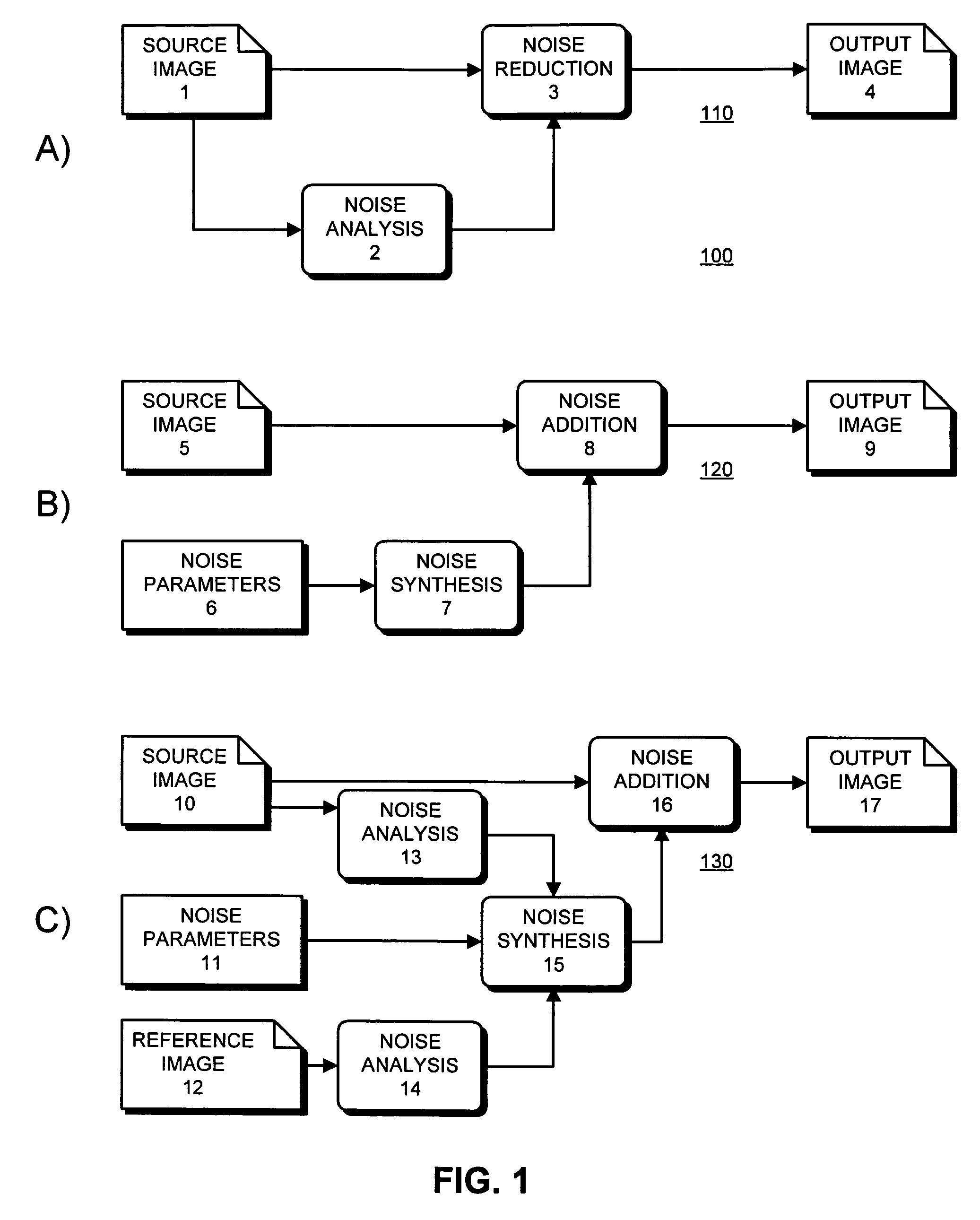
[0026]Referring to FIGS. 1(a), (b) & (c), there is shown three fundamentally different uses for the present invention.

[0027]FIG. 1a shows a noise reduction system 110 according to a one embodiment of the present invention. In this embodiment a source image 1 is fed into a noise analysis stage 2. The results of this analysis are used by a noise reduction stage 3 to produce an output image 4 with significantly less noise than the source image.

[0028]FIG. 1b shows a noise addition system 120 according to a her embodiment of the invention. Again there is a source image 5 and a set of user-specified noise parameters 6 which control the quantity and quality of the noise created in a noise synthesis stage 7. The resulting noise is then combined with the source image in a noise addition stage 8, resulting in an output image 9 which displays noise of the specified type.

[0029]FIG. 1c shows a noise matching system 130 according to still further embodiment of the present invention. In this embod...


PUM


Abstract

An apparatus for analyzing the broadband noise content of a digital image comprising the following: a means of automatically identifying regions of originally constant color in the image by analysis of the variance of pixel values of regions of the image; a means of automatically detecting and discarding regions deemed to be unrepresentative of the true noise content of an image, including under- and over-exposed regions; a means of allowing the user to manually select some or all required constant color regions if desired; and, a means of analyzing such constant color regions to generate a parametric or non-parametric model of the noise in the image, including frequency characteristic within and between channels and other characteristics such as phase which might describe structured noise.

Description

BACKGROUND OF THE INVENTION[0001]In the present context, noise is broadly defined as random variations in value among the pixels, that comprise a digitally represented image (an “image”), from an ideal representation of the subject of the image. The images can be real or synthetic. Many images include such noise as a result of the processes used to acquire the image from a real-world source or introduced during subsequent processing or reproduction. In the fields of photography, graphic design, visual special effects, production of printed materials, creation of composite photographs, film and video editing, encoding and transmission of images or film or video, and other related fields, it is desirable to control the exact noise content, in both type and amount, of the images being dealt with. For example, excessive noise is often unwanted, in that it may detract from perfect reproduction or interfere with certain subsequent technical processes. Conversely, it may be desirable to ad...

Claims


Application Information

Patent Timeline
Patent Type & Authority Patents(United States)
IPC IPC(8): G06K9/36G06T5/00G06T5/10G06V10/30
CPCG06K9/40G06T5/10G06T5/20G06T5/002G06T2207/20204G06T2207/20076G06T2207/10024G06T2207/20016G06V10/30
Inventor SHEKTER, JONATHAN MARTIN
Owner ADOBE SYST INC
Learn More