Image defect display system

Active Publication Date: 2006-01-24
ROMANIK PHILIP B +1
View PDF15 Cites 23 Cited by
  • Summary
  • Abstract
  • Description
  • Claims
  • Application Information

AI Technical Summary

Benefits of technology

[0009]Another aspect of the invention is that the composite image can be further annotated with known defect information supplied by the automated inspection system. Annotation can include text, highlighting regions where de

Problems solved by technology

As manufacturing equipment runs faster and faster, it is difficult to view the product without this frozen view.
Although these products offer flexibility in the rate that images can be displayed, they do not provide a mechanis

Method used


Image

  • Image defect display system
  • Image defect display system
  • Image defect display system

Examples


Embodiment Construction

[0015]Those of ordinary skill in the art will realize that the following description of the present invention is illustrative only and not in any way limiting. Other embodiments of the invention will readily suggest themselves to such skilled persons having the benefit of this disclosure. The various features of the invention will now be described with respect to the figures, in which like parts are identified with the same reference characters.

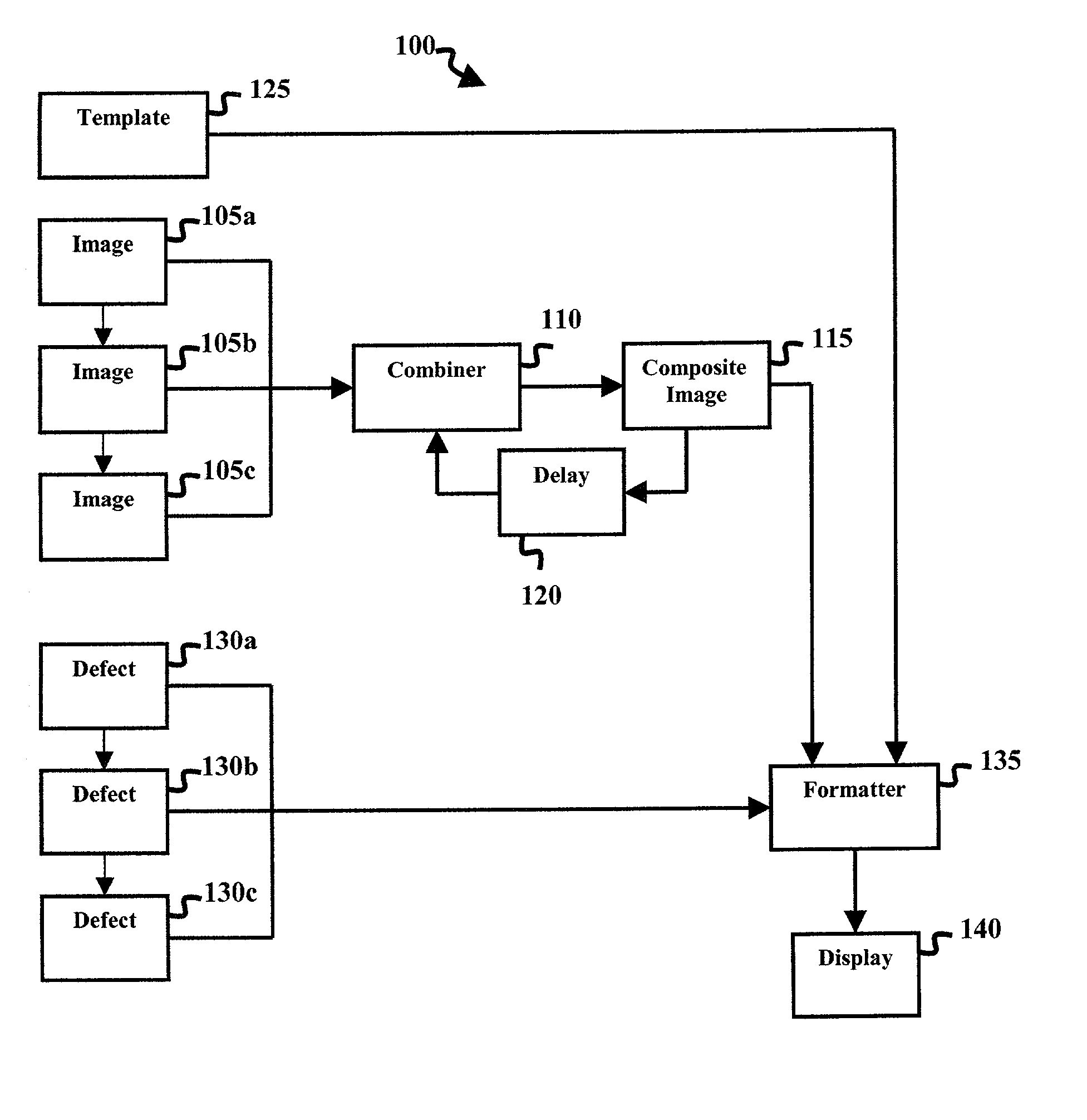
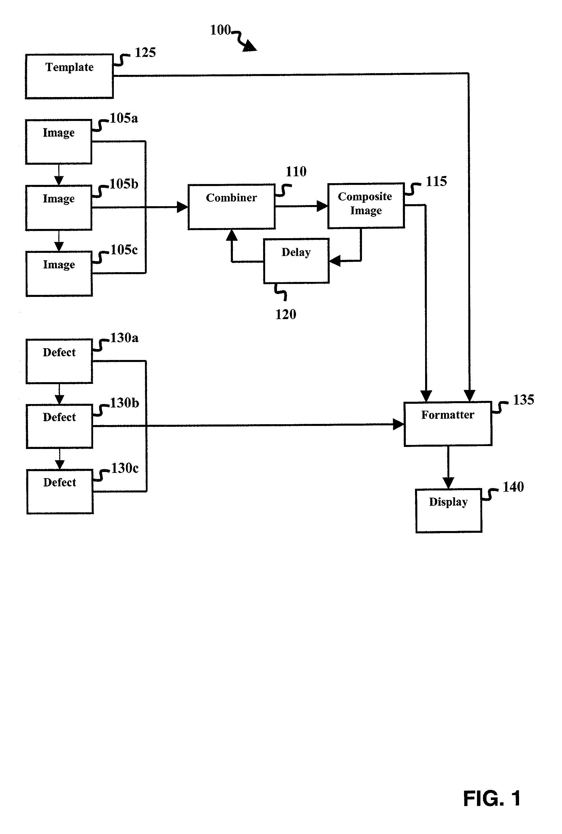
[0016]FIG. 1 is a block diagram illustrating a system 100 according to the invention for generating composite images from one or more source images for display. System 100 processes a multiplicity of images, e.g. image's 105a, 105b, 105c, referred to collectively as images 105. Images 105 are produced by an image inspection system and are either used directly from the inspection system or indirectly from an image database. In the preferred embodiment, these images are sequential images generated by the image inspection system. In the example ...


PUM


Abstract

A system for taking a sequence of images and converting them to a single composite image that contains the combined visual information of the defects found in the source images. The source images are aligned and manipulated, if necessary, such that they can be superimposed together. Optional image processing steps are applied to further enhance the defects. Both the number of input images and the algorithm used to combine these images can be adjusted to allow an observer to see a persistent display of the defects found in the images. Status, diagnostic and defect information, consisting of graphics and textual messages, are then applied to the composite image for display.

Description

CROSS REFERENCE TO RELATED APPLICATIONS[0001]Not ApplicableSTATEMENT REGARDING FEDERALLY SPONSORED RESEARCH OR DEVELOPMENT[0002]Not ApplicableREFERENCE TO A MICROFICHE APPENDIX[0003]Not ApplicableBACKGROUND OF THE INVENTION[0004]Image inspection systems analyze digital images to find defects or other abnormalities. Many machine vision systems expect every object passing under the camera to be identical to every other object. Through training, these systems can detect imperfections in a product so that it can be labeled, sorted, or rejected. The data that describes the defects is usually recorded such that process improvements can be made to prevent these defects from occurring in the future. Most systems also include a video monitor to display the most recent part that was inspected. This serves as a visual check of what the process is doing. Vision systems often include graphics or other overlay information to identify any problems that were found. When another object passes under ...

Claims


Application Information

Patent Timeline
IPC IPC(8): G06K9/36G06T3/00G06T5/50G06T7/00
CPCG06T7/0004G06T5/50
Inventor ROMANIK, PHILIP B.MUNTZ, AMY H.
Owner ROMANIK PHILIP B
Why Eureka
Try Eureka