Dynamoelectric machine winding joining method

Inactive Publication Date: 2006-01-31
MITSUBISHI ELECTRIC CORP
View PDF7 Cites 27 Cited by
  • Summary
  • Abstract
  • Description
  • Claims
  • Application Information

AI Technical Summary

Benefits of technology

[0018]Therefore, the joint end portions being joined are brought into close contact while ensuring a clearance between the pairs of the joint end portions being joined, thereby it is not necessary to rigorously manage the pressure

Problems solved by technology

As a result, one problem has been that arc heat rises, giving rise to degradation of an electrically-insulating coating on the U-shaped copper wires, thereby making electrical insulation poor.
In the worst cases, the free ends 50 on the inner circumferential side are too far apart from each other, and there has been a risk that they could not be joined together.
As a result, another problem ha

Method used


Image

  • Dynamoelectric machine winding joining method
  • Dynamoelectric machine winding joining method
  • Dynamoelectric machine winding joining method

Examples


embodiment 1

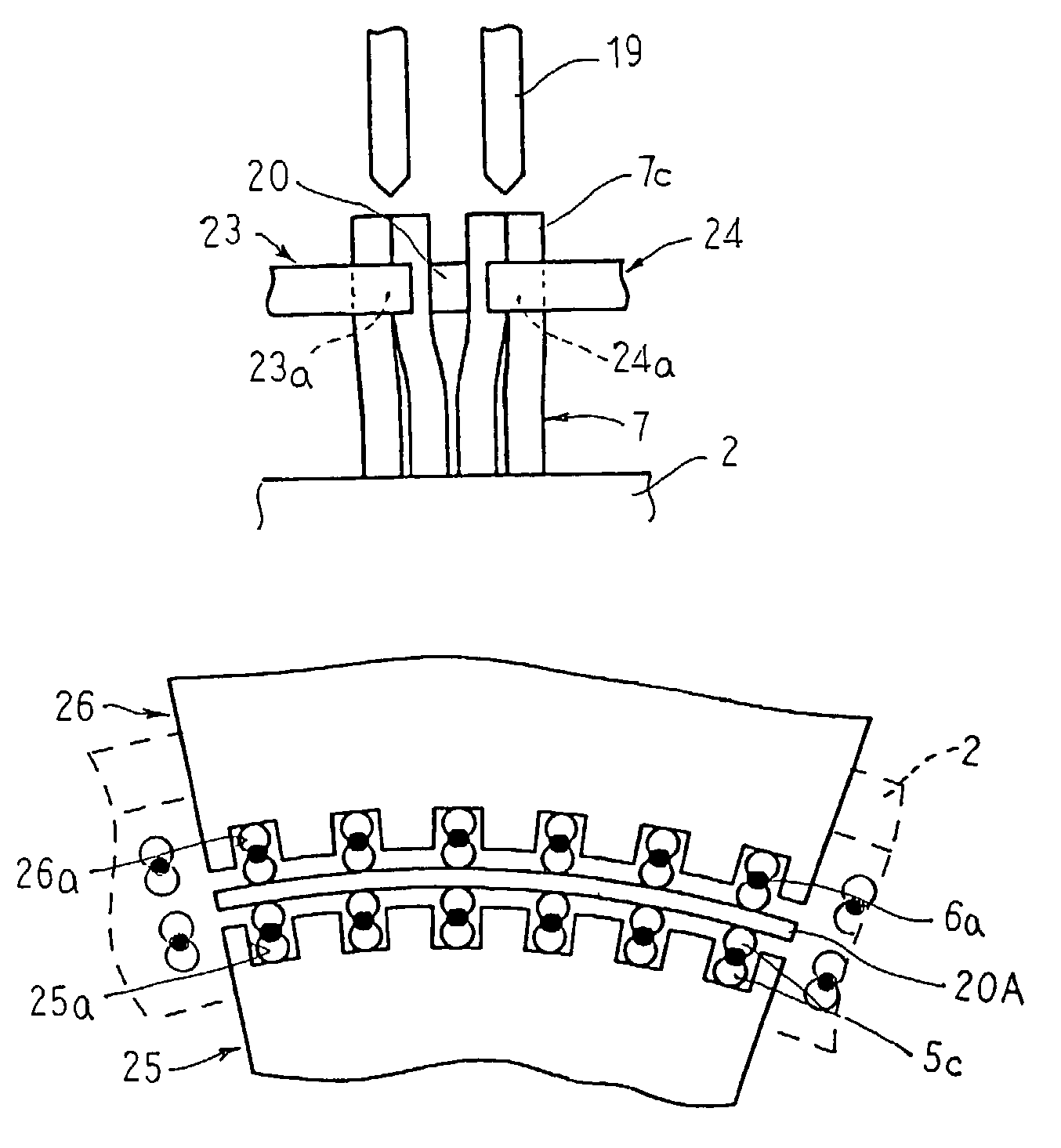
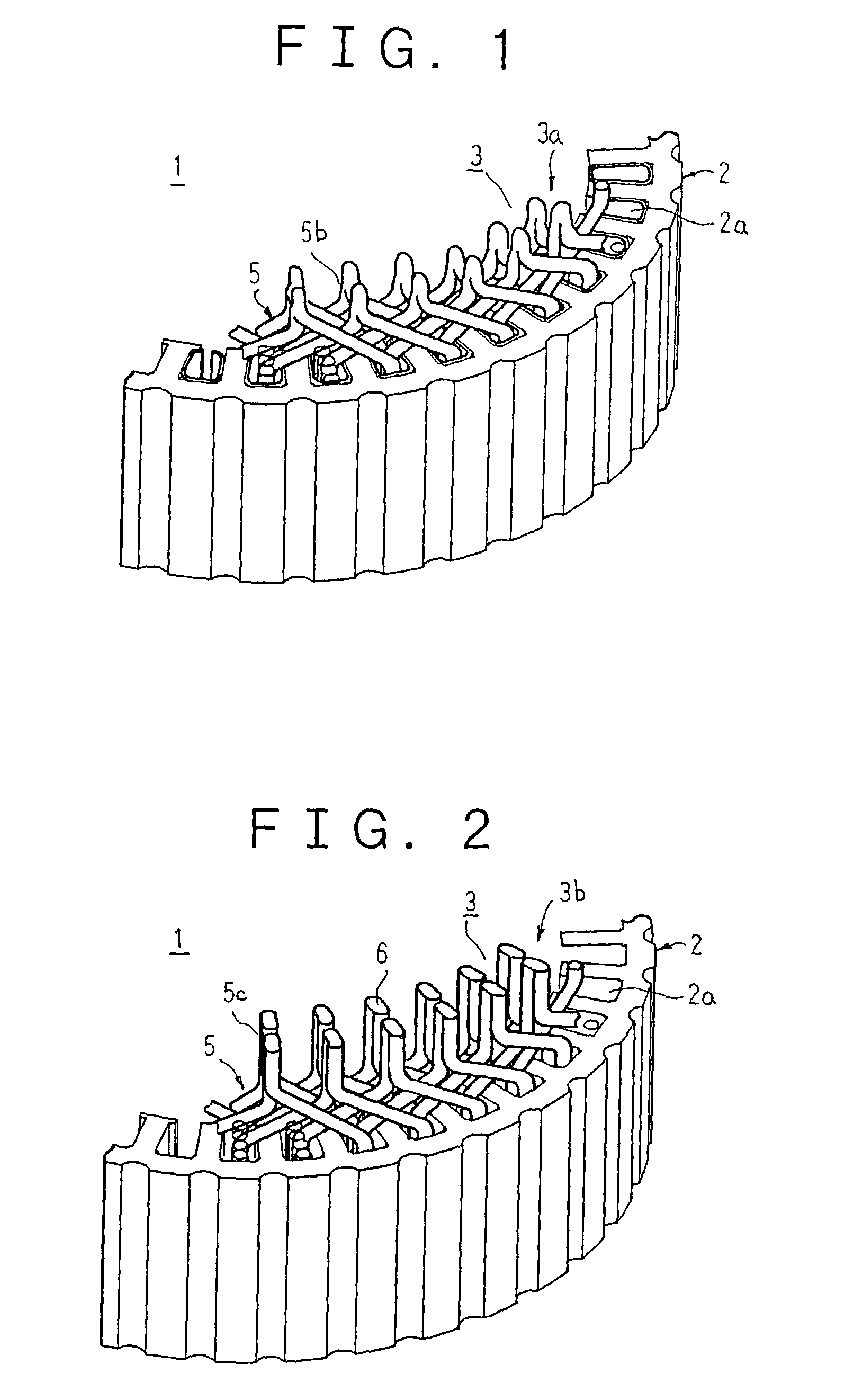
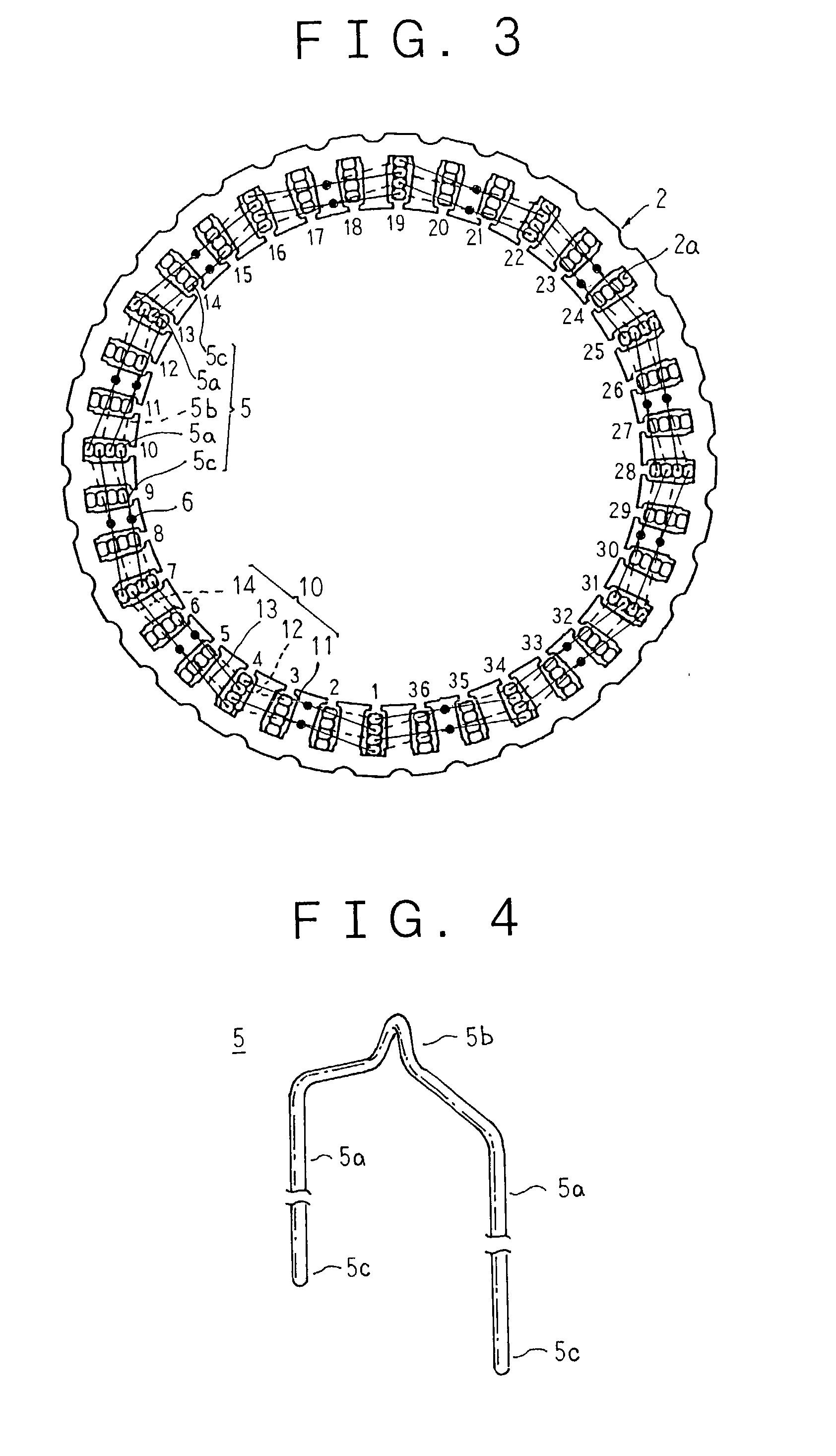
[0039]FIG. 1 is a perspective from a first end of a stator for an automotive alternator manufactured by a dynamoelectric machine winding joining method according to Embodiment 1 of the present invention, FIG. 2 is a perspective from a second end of the stator for an automotive alternator manufactured by the dynamoelectric machine winding joining method according to Embodiment 1 of the present invention, FIG. 3 is an end elevation explaining connections in a first stator winding phase portion of the stator shown in FIG. 1, FIG. 4 is a perspective showing a conductor segment constituting a stator winding of the stator shown in FIG. 1, and FIGS. 5 and 6 are a perspective and an end elevation, respectively, explaining the dynamoelectric machine winding joining method according to Embodiment 1 of the present invention.

[0040]Moreover, in FIG. 3, 1 through 36 represent slot numbers, broken lines indicate windings at a first end of the stator core, solid lines indicate windings at a second ...

embodiment 2

[0068]In Embodiment 2, the free ends 5c are joined together by soldering instead of TIG welding. Moreover, the rest of this embodiment is constructed in a similar manner to Embodiment 1 above.

[0069]Thus, similar effects to those in Embodiment 1 above can also be achieved in Embodiment 2.

[0070]Furthermore, in Embodiment 2, because the free ends 5c are joined together by soldering, the joint portions become a spherically-bulging shape. However, because the clearance between the pairs of free ends 5c is ensured, short-circuiting among the joint portions is suppressed.

embodiment 3

[0071]In Embodiment 3, as shown in FIG. 8, conductor segments (electrical conductors) 7 formed with a general U shape in which a pair of straight portions 7a are linked by a generally V-shaped return portion 7b by bending a copper wire having a rectangular cross section coated with an electrical insulator are used, and as shown in FIG. 9 and FIG. 10, first and second radial restraining members 23 and 24 made of a stainless steel in which first and second recess portions 23a and 24a for restraining free ends 7c (joint end portions) are formed on tip portions are used. Moreover, the rest of this embodiment is constructed in a similar manner to Embodiment 1 above.

[0072]In Embodiment 3, in a similar manner to Embodiment 1 above, the conductor segments 7 are inserted from the first end surface of the stator core 2 two by two into pairs of slots 2a three slots apart, and at the second end surface of the stator core 2, thirty-six rows of four free ends 7c are arranged into an annular shape...


PUM

PropertyMeasurementUnit
aaaaaaaaaa

Abstract

An intermediate holding member is inserted between a second free end and a third free end from an inner circumferential side in a radial direction, a first radial restraining member presses against a free end at an innermost circumference from radially inside, and a second radial restraining member presses against a free end at an outermost circumference from radially outside. Next, a voltage is supplied between a torch and the members, an inert gas is supplied to the torch, and an arc discharge is generated between the torch and the free ends, welding the radially-adjacent free ends.

Description

BACKGROUND OF THE INVENTION[0001]1. Field of the Invention[0002]The present invention relates to a dynamoelectric machine winding joining method, and particularly relates to a winding joining method applied to joining a stator winding for an alternator mounted to an automotive vehicle such as a passenger car or a truck.[0003]2. Description of the Related Art[0004]Conventionally, in the joining of dynamoelectric machine stator windings, a joining method is generally adopted in which an arc is discharged between an electrode and a winding joint portion and the heat thereof is used to fuse the winding together, as described in Japanese Patent Non-Examined Laid-Open No. 2000-350421, for example.[0005]A conventional dynamoelectric machine winding joining method such as described in Japanese Patent Non-Examined Laid-Open No. 2000-350421, for example, will now be explained with reference to FIG. 19.[0006]First, the construction of a stator to which this winding joining method is applied wi...

Claims


Application Information

Patent Timeline
IPC IPC(8): H02K15/00H02K15/16H02K15/14H02K3/50H02K3/04H02K15/04H02K15/085
CPCH02K15/0056H02K15/0081Y10T29/49012Y10T29/53143Y10T29/49071Y10T29/49009H02K3/28H02K3/50H02K3/14H02K15/064
Inventor TAMURA, SYUUICHIAKITA, HIROYUKITAKIZAWA, TAKUSHIOOHASHI, ATSUSHI
Owner MITSUBISHI ELECTRIC CORP
Why Eureka
Try Eureka