
Alignment-tolerant lens structures for acoustic force actuation of cantilevers

a technology of aligning tolerance and lens structure, applied in the field of driving systems, can solve the problem of reducing the sensitivity of resonance effects to spacing between

Inactive Publication Date: 2006-01-31
PALO ALTO RES CENT INC
View PDF6 Cites 11 Cited by
  • Summary
  • Abstract
  • Description
  • Claims
  • Application Information

AI Technical Summary

Benefits of technology

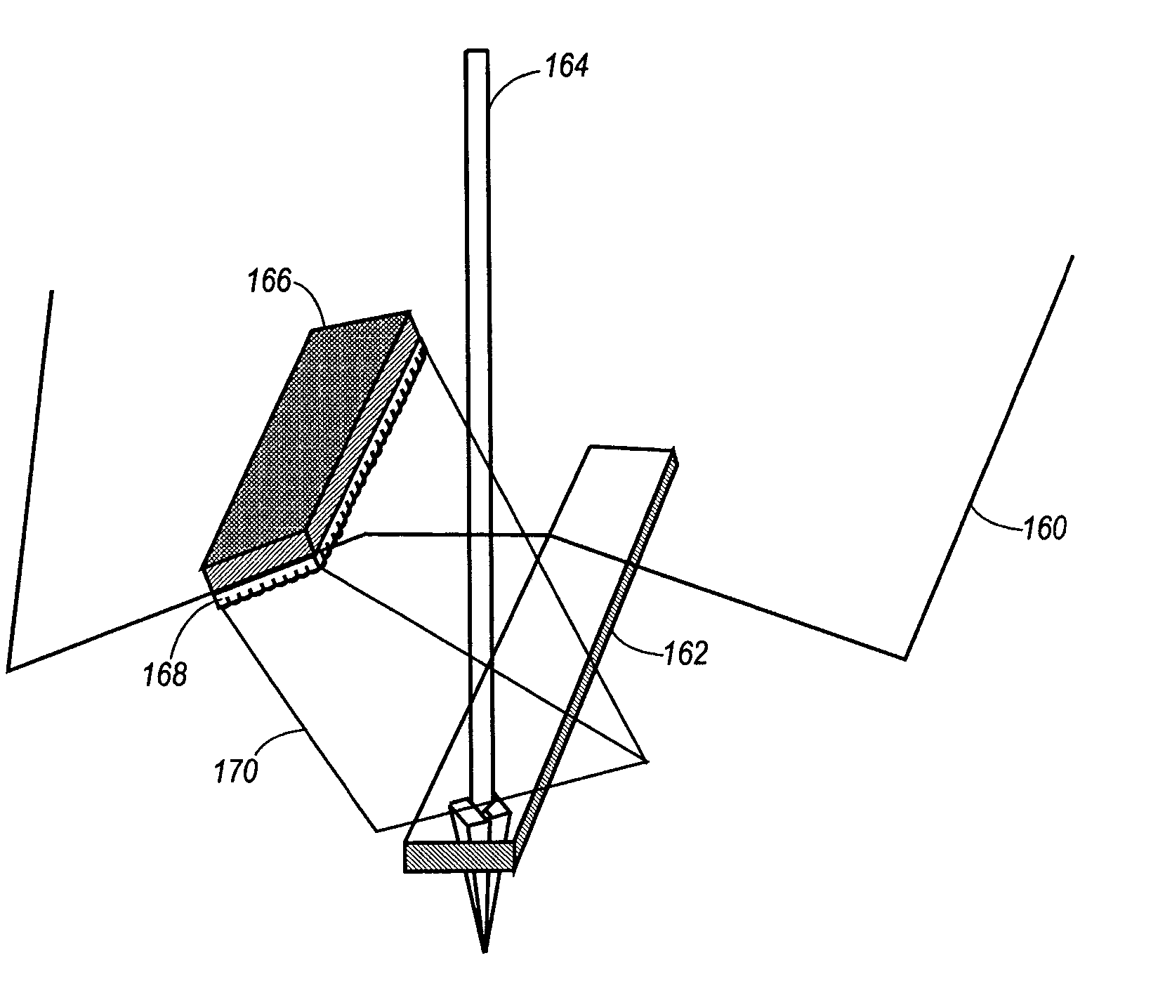
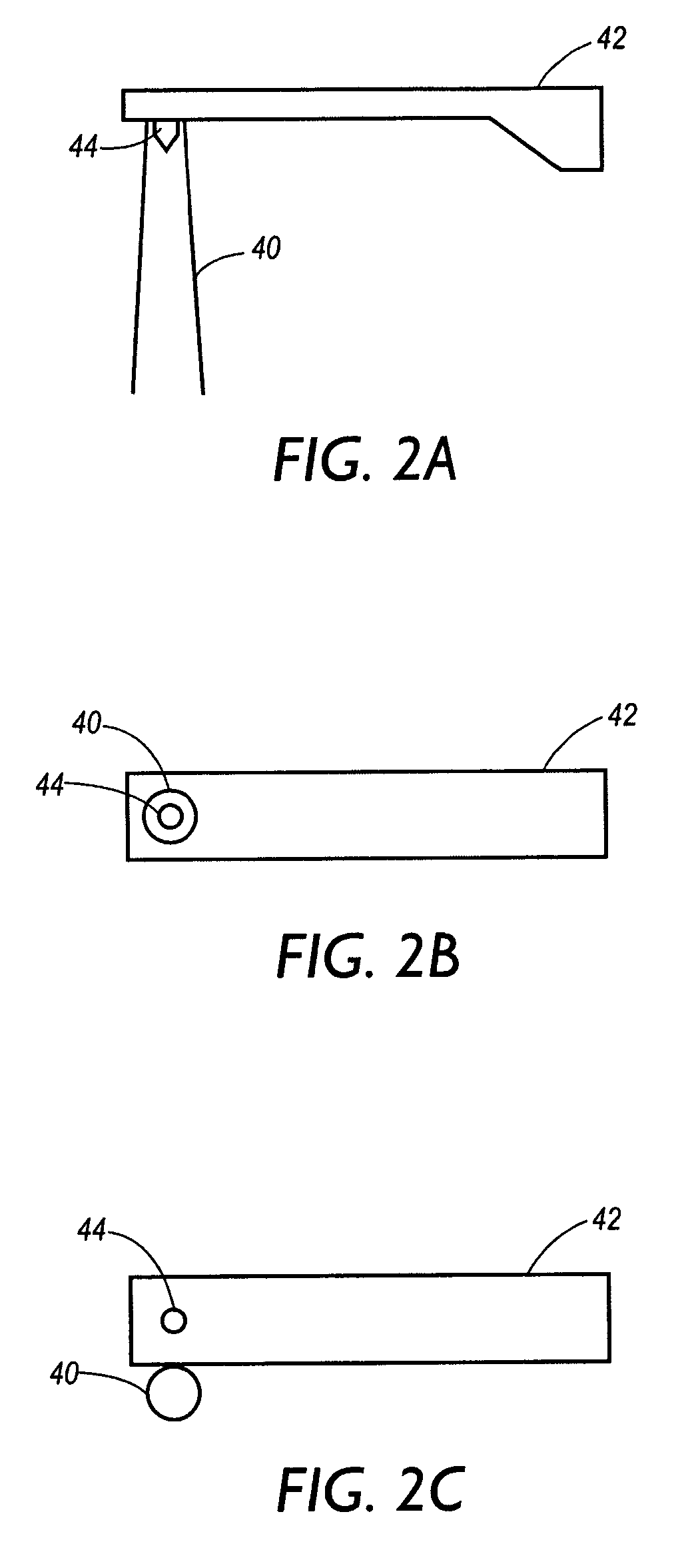
[0022]In accordance with one aspect of the present invention, a cantilever of a probe-based instrument is deflected by directing a beam of ultrasonic acoustic energy at the cantilever to apply acoustic radiation pressure to the cantilever. The energy is generated by an acoustic actuator. The transmitted beam preferably is focused using a cylindrical lens, providing a beam tightly focused in one dimension and unfocused in a second dimension. In accordance with another aspect of the present invention, a power source such as an RF signal generator is operated so as to spread the spectrum of acoustic radiation on a time scale that is short or comparable to the acoustic roundtrip time. Such a design diminishes the resonance effects sensitivity to spacing between the cantilever and the acoustic source.

Problems solved by technology

Such a design diminishes the resonance effects sensitivity to spacing between the cantilever and the acoustic source.

Method used


Image

  • Alignment-tolerant lens structures for acoustic force actuation of cantilevers
  • Alignment-tolerant lens structures for acoustic force actuation of cantilevers
  • Alignment-tolerant lens structures for acoustic force actuation of cantilevers

Examples


Embodiment Construction

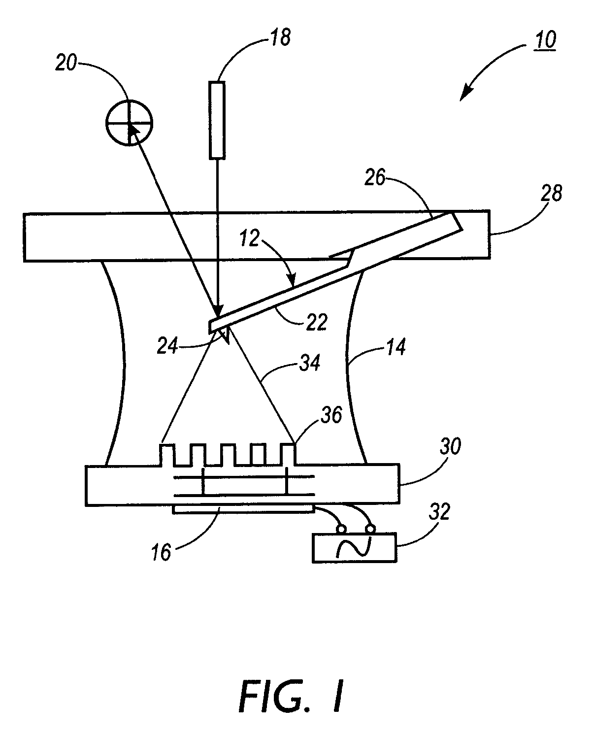
[0037]Referring to FIG. 1, an AFM 10 which incorporates a cantilever deflecting system according to the present application is illustrated. The AFM 10 includes a probe 12 configured to operate in a liquid contained within a cell 14, an ultrasonic actuator 16 for generating acoustic waves, and a detector system (18, 20). Probe 12 includes a cantilever 22 and a tip 24 mounted or otherwise provided on a free end of the cantilever 22. The cantilever, in one embodiment, is made of silicon and may have any of among a number of spring constants and corresponding fundamental resonances. In one example, a cantilever having a spring constant of 0.148 N / m will have a fundamental resonance around 4.6 kHz in water.

[0038]The base of the cantilever 22 is fixed to an optically transparent probe support 26, which may fit into a commercial AFM scanhead 28. The fluid cell 14 is positioned beneath the scanhead 28 with the probe 12 closely located. An ultrasonically transparent substrate 30, preferably ...


PUM


Abstract

In accordance with one aspect of the present invention, a cantilever of a probe-based instrument is deflected by directing a beam of ultrasonic acoustic energy at the cantilever to apply acoustic radiation pressure to the cantilever. The energy is generated by an acoustic actuator. The transmitted beam preferably is focused using a cylindrical lens, providing a beam tightly focused in one dimension and unfocused in a second dimension. In accordance with another aspect of the present invention, a power source such as an RF signal generator is operated so as to spread the spectrum of acoustic radiation on a time scale that is short or comparable to the acoustic roundtrip time. Such a design diminishing the resonance effects and sensitivity to spacing between the cantilever and the acoustic source.

Description

BACKGROUND OF THE INVENTION[0001]The present application is directed to driving systems, and more particularly to a method and apparatus for driving a cantilever through the use of acoustic wave pressure generated by an ultrasonic actuator.[0002]Scanning probe microscopes (SPMs) represent a category of probe-based instruments designed to characterize a surface of a sample at an atomic level, through the monitoring of an interaction between a sample and a tip on a cantilever probe. This interaction is primarily a scanning operation between the tip and sample, whereby data regarding characteristics of the surface is acquired and used to generate an image of the sample region. The image data is commonly acquired via a raster scan of the sample.[0003]A particular type of SPM is known as an atomic force microscope (AFM), which functions by measuring local properties of a sample, such as height, optical absorption, magnetism or other measurable characteristic. The resulting image will res...

Claims


Application Information

Patent Timeline
IPC IPC(8): G01B11/30G01Q60/24
CPCY10S977/872G01Q60/32
Inventor ELROD, SCOTT A.
Owner PALO ALTO RES CENT INC
Learn More