Balancer structure for engine

a technology of balancer structure and engine, which is applied in the direction of machines/engines, springs/dampers, vibration suppression adjustments, etc., can solve the problems of disassembly and assembly of the crankshaft, and achieve the effect of reducing the length of the crankcase in the direction perpendicular to the crankshaft, and preventing a large torque from the cranksha

Active Publication Date: 2006-01-31
YAMAHA MOTOR CO LTD
View PDF4 Cites 21 Cited by
  • Summary
  • Abstract
  • Description
  • Claims
  • Application Information

AI Technical Summary

Benefits of technology

[0008]An embodiment of the present invention is directed to a balancer structure for an engine in which balancer gears on a first and a second balancer shaft provided parallel to a crankshaft are driven for rotation by a crank gear of the crankshaft. The first balancer shaft is provided on one side of a normal plane including the axis of the crankshaft, and the second balancer shaft is provided on the other side. On the second balancer shaft is provided a counter gear for transmitting the rotation of the crankshaft to a main shaft of a transmission mechanism.
[0009]A torque damper for preventing a large torque from the crankshaft from being transmitted directly to the main shaft is provided in a drive force transmission path for transmitting a drive force of the crankshaft to the main shaft, on the downstream side from the balancer gear on the second balancer shaft.
[0010]The main shaft is provided on the opposite side from the crankshaft, with the balancer shaft placed therebetween. A shift drum is provided between the main shaft and the second balancer shaft.
[0011]The first balancer shaft is disposed on one side of a horizontal plane including the axis of the crankshaft, and the second balancer shaft is provided on the other side.
[0012]The engine has front and rear cylinders disposed forming a V-bank and is a V-type, two-cylinder engine mounted on a vehicle body, with the crankshaft oriented in the lateral direction. The first balancer shaft is disposed in front of the normal plane including the axis of the crankshaft and above the horizontal plane including the axis. The second balancer shaft is disposed behind the normal plane and below the horizontal plane. A drive shaft of the transmission mechanism is disposed rearward of the second balancer shaft and near the horizontal plane. The main shaft is disposed above the horizontal plane and between the drive shaft and the second balancer shaft. A shift drum is disposed such that its axis is located in a region surrounded by axes of the main shaft, the drive shaft and the second balancer shaft.
[0013]According to an embodiment of the present invention, the second balancer shaft is provided with a counter gear for transmitting a rotation of the crankshaft to the main shaft, so that the second balancer shaft is used as a counter shaft as well. Therefore, the counter shaft is dispensed and the length of the crankcase in the direction perpendicular to the crankshaft can be decreased by the amount corresponding to the layout space of the counter shaft.

Problems solved by technology

However, when the foregoing phase-pin crank is adopted, since pins with different phases are connected, a web is required between pins and the distance between crank journals as supporting points is necessarily increased compared with a coaxial pin crank, which is disadvantageous to the strength or the rigidity of the crankshaft.

Method used


Image

  • Balancer structure for engine
  • Balancer structure for engine
  • Balancer structure for engine

Examples


Embodiment Construction

[0044]Now, embodiments of this invention will be described below with reference to the accompanying drawings.

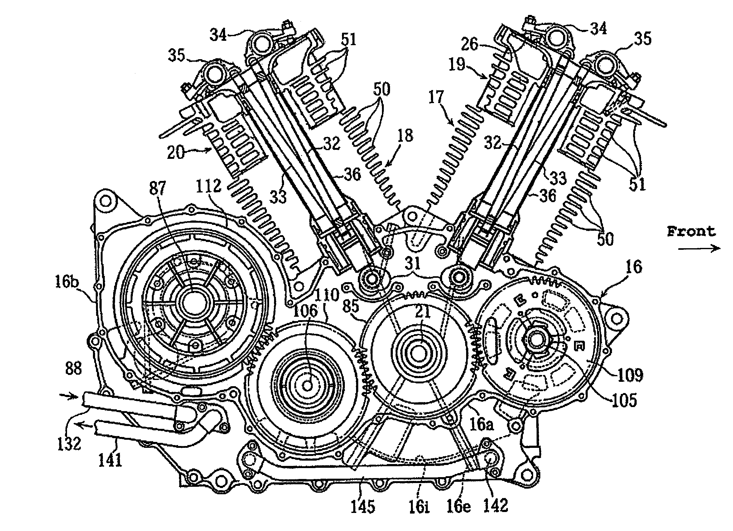
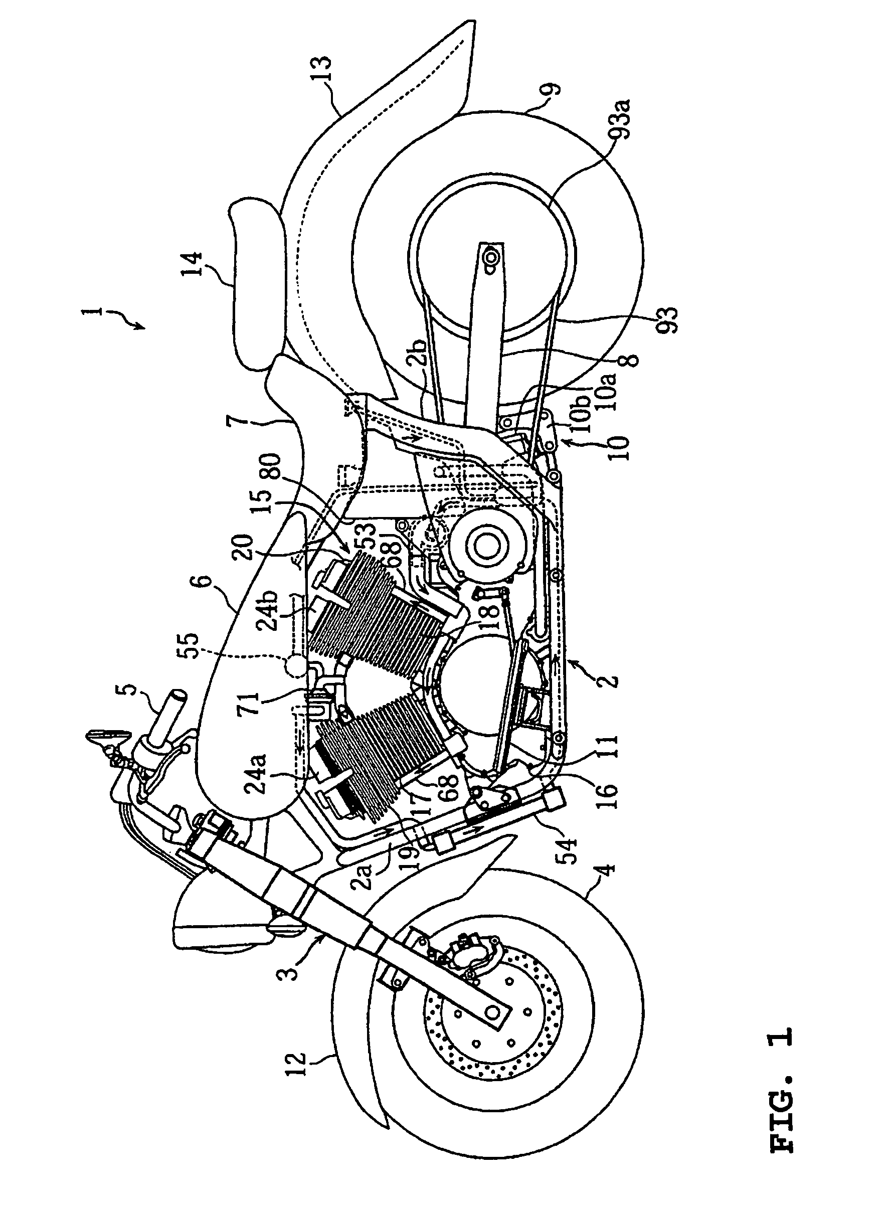
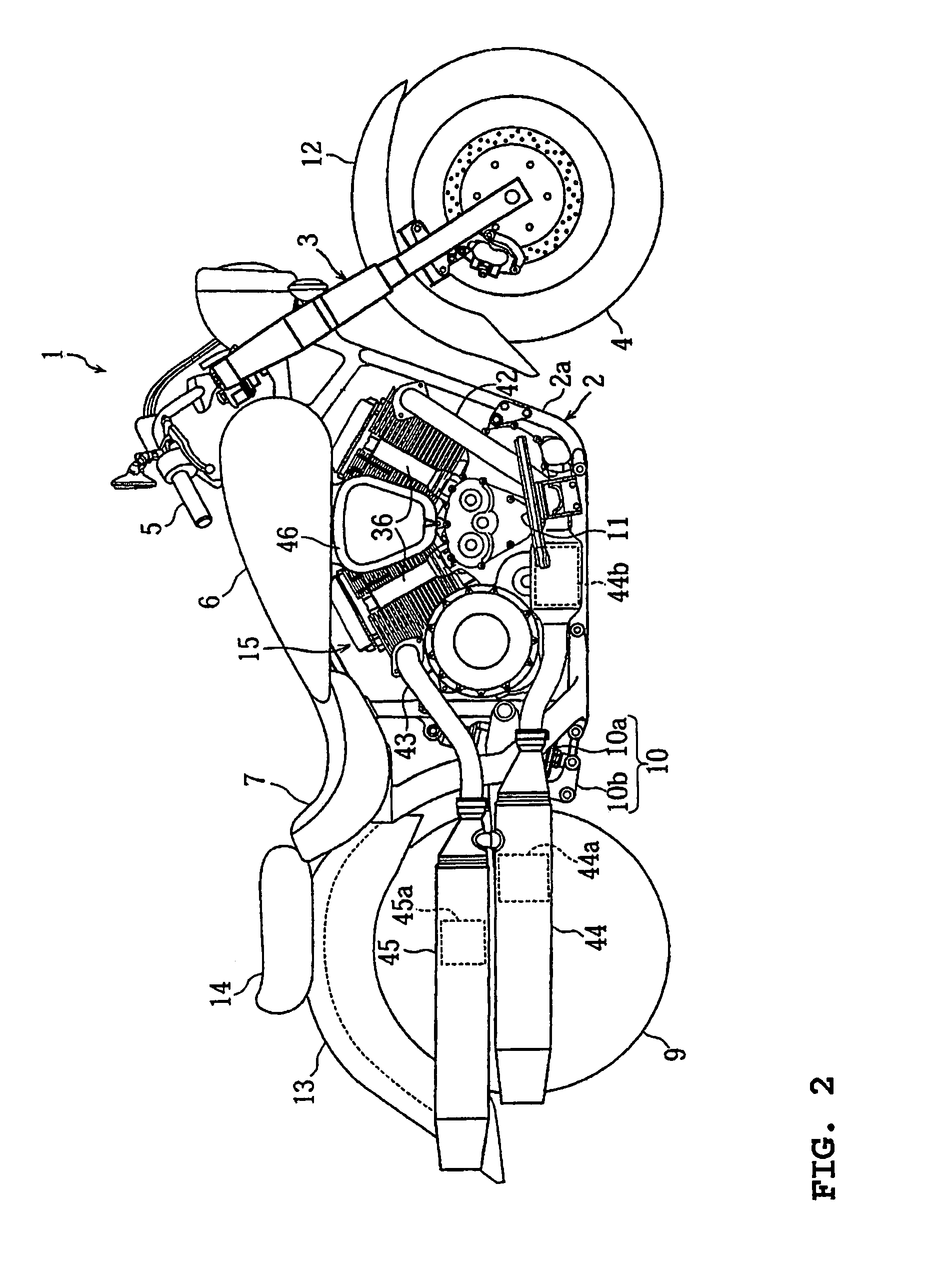
[0045]FIG. 1–FIG. 20 are views illustrating a balancer structure for an engine according to an embodiment of the present invention. FIG. 1 and FIG. 2 are left side and right side views, respectively, of a motorcycle carrying an engine of this embodiment. FIG. 3 and FIG. 4 are sectional right side views of the engine. FIG. 5 is a sectional rear view of the engine. FIG. 6 is a sectional plan view of the engine. FIG. 7 is a sectional plan view of a power transmission section of the engine. FIG. 8 is an overall view of a partial water cooling system of the engine. FIG. 9 is a sectional side view of a water pump section of the partial water cooling system. FIG. 10 is a sectional view taken along the line X—X of FIG. 9. FIG. 11 is a bottom view of a cylinder head. FIG. 12 is a sectional view taken along the line XII—XII of FIG. 11. FIG. 13 is a block diagram of the partial water co...


PUM


Abstract

A balancer structure for an engine includes a first balancer shaft, a second balancer shaft, a crankshaft having a crank gear and balancer gears on the first and second balancer shafts provided parallel to the crankshaft and driven for rotation by the crank gear. The first balancer shaft is provided on one side of a normal plane including an axis of the crankshaft, and the second balancer shaft is provided on another side. On the second balancer shaft is provided a counter gear for transmitting a rotation of the crankshaft to a main shaft of a transmission mechanism.

Description

BACKGROUND OF THE INVENTION[0001]1. Field of the Invention[0002]This invention relates to a balancer structure for an engine in which two balancer shafts are provided for one crankshaft.[0003]2. Description of Related Art[0004]Of engines with a large displacement, single-cylinder or V-type two-cylinder engines, for example, are in use in a lower engine speed range compared with multi-cylinder engines such as four-cylinder engines. Therefore, a vibration due to an inertia force becomes dominant. In some engines of this type, for the purpose of canceling the inertia force, a phase-pin crank has been adopted, which has a phase difference in the position of the crank pins or a two-shaft primary balancer has been adopted, which has two balancer shafts. By the way, in a one-shaft primary balancer with one shaft, the moment of the inertia force cannot be canceled and a vibration reducing effect is small especially in engines with a large displacement.[0005]However, when the foregoing phase...

Claims


Application Information

Patent Timeline
Patent Type & Authority Patents(United States)
IPC IPC(8): F02B75/06F02B77/00F16F15/121F16F15/26
CPCF16F15/265F02B75/06
Inventor TAKEUCHI, YOSHIHIKO
Owner YAMAHA MOTOR CO LTD
Why Eureka
Try Eureka