Ultra fine particle film forming method and apparatus

a technology of ultra fine particles and film forming, which is applied in the direction of electrical equipment, metal-working equipment, metal-coating processes, etc., can solve the problems of uneven density of film, adversely affecting later deposition, and uneven surfa

Inactive Publication Date: 2006-01-31
NAT INST OF ADVANCED IND SCI & TECH
View PDF10 Cites 80 Cited by
  • Summary
  • Abstract
  • Description
  • Claims
  • Application Information

AI Technical Summary

Problems solved by technology

This conventional ultra fine particle film forming method is, however, associated with some problems that the film surface is not smooth and flat and the density of the film is not uniform.
Specifically, with the conventional ultra fine particle film forming method, if ultra fine particles contain defective particles (such as particles having a diameter of 1 μm or larger and insufficiently accelerated particles) unable to physically form a film, these defective particles are mixed in a deposit on a substrate.
As shown in a microscopic photograph of FIG. 11, the film surface is very rough, which adversely affects later deposition.
If such a conventional film forming method is applied to forming a ceramic electronic component which is required to have a homogeneously controlled fine structure of the film, excellent electrical characteristics cannot be expected.
It is also practically difficult to make the amount of fine particles to be jetted out of a nozzle uniform and constant, so that the film thickness changes at positions.
It is also difficult to control a film thickness and a surface uniformity, which becomes a large obstacle against forming films having uniform performance and good film quality.
Such irregular film thickness and surface roughness become a critical issue when the conventional method is applied to forming an optical thin film.

Method used


Image

  • Ultra fine particle film forming method and apparatus
  • Ultra fine particle film forming method and apparatus
  • Ultra fine particle film forming method and apparatus

Examples


Embodiment Construction

[0026]Embodiments of the invention will be described with reference to the accompanying drawings.

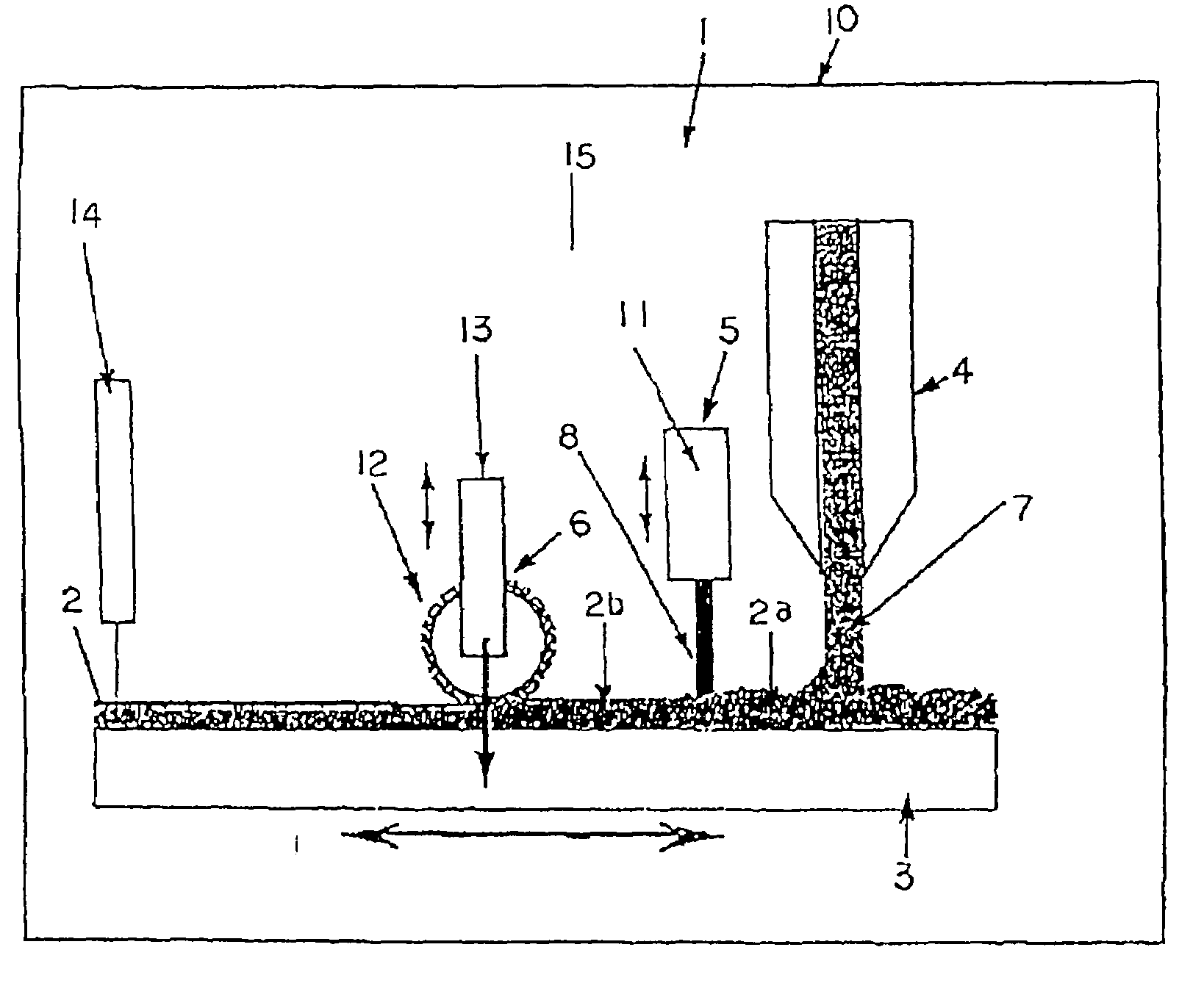
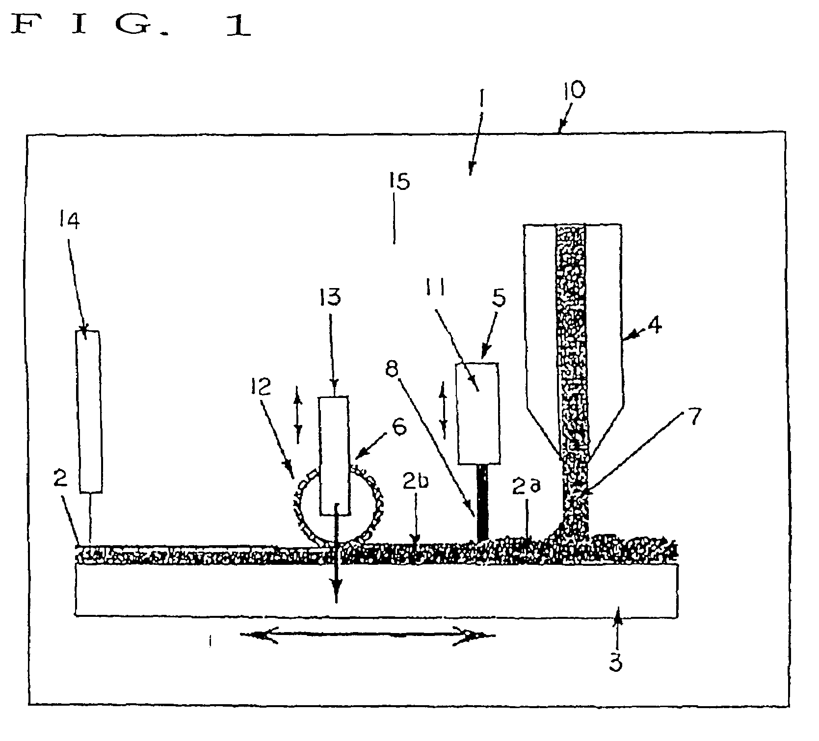
[0027]In FIG. 1, reference numeral 1 represents a planarized ultra fine particle film forming apparatus. The planarized ultra fine particle film forming apparatus 1 has a substrate 3 and a nozzle 4 disposed in a chamber 10. The nozzle 4 is an example of a ultra fine particle supply apparatus. The substrate 3 is used for supporting a film to be formed thereon. An attached fine particle removal apparatus 5 and a film surface processing apparatus 6 are disposed along a substrate motion path. The attached fine particle removal apparatus 5 and film surface processing apparatus 6 constitute a planarizing apparatus 15 for planarizing a deposited film 2a. The chamber 10 may be a vacuum chamber capable of reducing the inner pressure. If the vacuum chamber is used as the chamber 10, the vacuum degree is set to about 10 to 200 Torr, or preferably to about 100 Torr.

[0028]The nozzle 4 is used for sup...


PUM

PropertyMeasurementUnit
incidence angleaaaaaaaaaa

Abstract

A ultra fine particle film forming apparatus is provided which is capable of forming a ultra fine particle film which has ultra fine particles sufficiently bonded together, sufficient density, flat surface and uniform density. A planarized ultra fine particle film forming method for forming a planarized ultra fine particle film from a deposited film of ultra fine particles formed by supplying the ultra fine particles to a substrate, the method comprising one or more of a planarizing step of planarizing a surface of the deposited film of the ultra fine particles supplied to the substrate.

Description

RELATED APPLICATION[0001]This application is a continuing divisional application of my application Ser. No.: 09 / 752,360 filed Dec. 29, 2000 now U.S. Pat. No. 6,827,634, the entire contents and disclosure of which are considered as being part of the disclosure of this continuing divisional application and are hereby incorporated by reference herein in their entirety.BACKGROUND OF THE INVENTION[0002]a) Field of the Invention[0003]The present invention relates to techniques of supplying ultra fine particles of ceramic, metal and the like not larger than about 1 μm to a substrate to form a ultra fine particle film. Such techniques of forming a ultra fine particle film are applied to the technical fields of forming a functional ceramic thin film, a metal thin film or the like on a substrate.[0004]b) Description of the Related Art[0005]As one of techniques of forming a ultra fine particle film, it is known to mix ultra fine particles with transport gas and spray the particles mixed with t...

Claims


Application Information

Patent Timeline
Patent Type & Authority Patents(United States)
IPC IPC(8): B24B49/00B24B37/04B24B57/04B24C1/00B24C1/10B24C5/04C23C4/18C23C24/00C23C24/04H01L41/314H05K3/10H05K3/14
CPCB24C1/00H01L41/314B24C5/04C23C4/18C23C24/00C23C24/04H05K3/102H05K3/14B24C1/10H05K2203/0143H05K2203/025H05K2203/0257H05K2203/0278H05K2203/105H05K2203/1344H10N30/074
Inventor AKEDO, JUN
Owner NAT INST OF ADVANCED IND SCI & TECH
Why Eureka
Try Eureka