
External disconnect mechanism integrated with an electrical system enclosure

a technology of electrical system enclosure and external disconnect mechanism, which is applied in the direction of contact mechanism, switchgear with a retractable carriage, relay, etc., can solve the problems of not being able to access the inverter from outside, requiring additional assembly, and expensive disconnection enclosure, etc., and achieving simple, cost-effective, reliable and reliable solutions to the above-mentioned application.

Inactive Publication Date: 2006-01-31
WILEY ELECTRONICS
View PDF14 Cites 29 Cited by
  • Summary
  • Abstract
  • Description
  • Claims
  • Application Information

AI Technical Summary

Benefits of technology

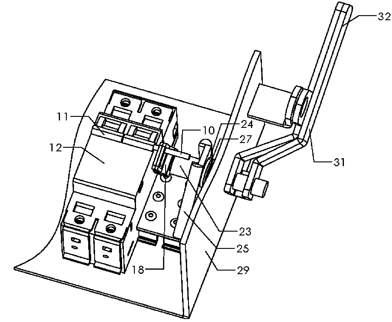
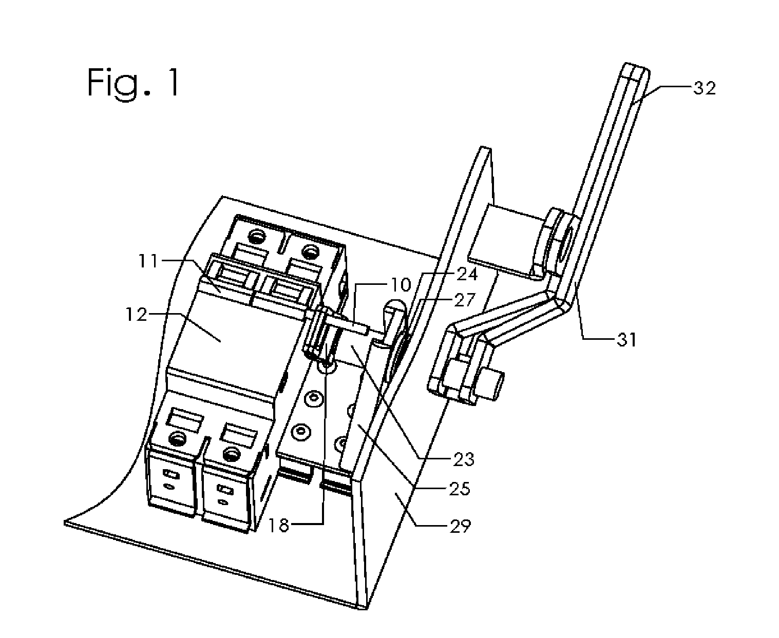
[0022]The present invention is an addition to the enclosure of a photovoltaic inverter or other electrical system, which already contains circuit breakers to meet overcurrent protection requirements. A simple mechanism allows external manual switching of the breakers, thus eliminating the need for a separate external disconnect switch and enclosure.

Problems solved by technology

The disconnect enclosure is costly, bulky, and requires additional assembly at the time of system installation.
The circuit breakers are generally protected from exposure to weather by a watertight enclosure, however, and so are not accessible from outside the inverter.
There exist inventions with a circuit breaker in an enclosure, which are operated by an external lever, but none of them directly address the needs of the above application in a simple, cost-effective, reliable manner.
This mechanical advantage is unnecessary for the photovoltaic inverter and would therefore increase cost unnecessarily.
Modern circuit breakers have a self-contained snap-action mechanism that makes these intricate mechanisms unnecessary.
Again, including this unnecessary feature is undesirable.
In general, all of the above inventions are more complicated than required for this application.
They will therefore be more expensive and more difficult to manufacture.
They will also have an increased likelihood of breakdown and increased cost of maintenance.

Method used


Image

  • External disconnect mechanism integrated with an electrical system enclosure
  • External disconnect mechanism integrated with an electrical system enclosure
  • External disconnect mechanism integrated with an electrical system enclosure

Examples


Embodiment Construction

—FIGS. 1 THROUGH 6—PREFERRED EMBODIMENT

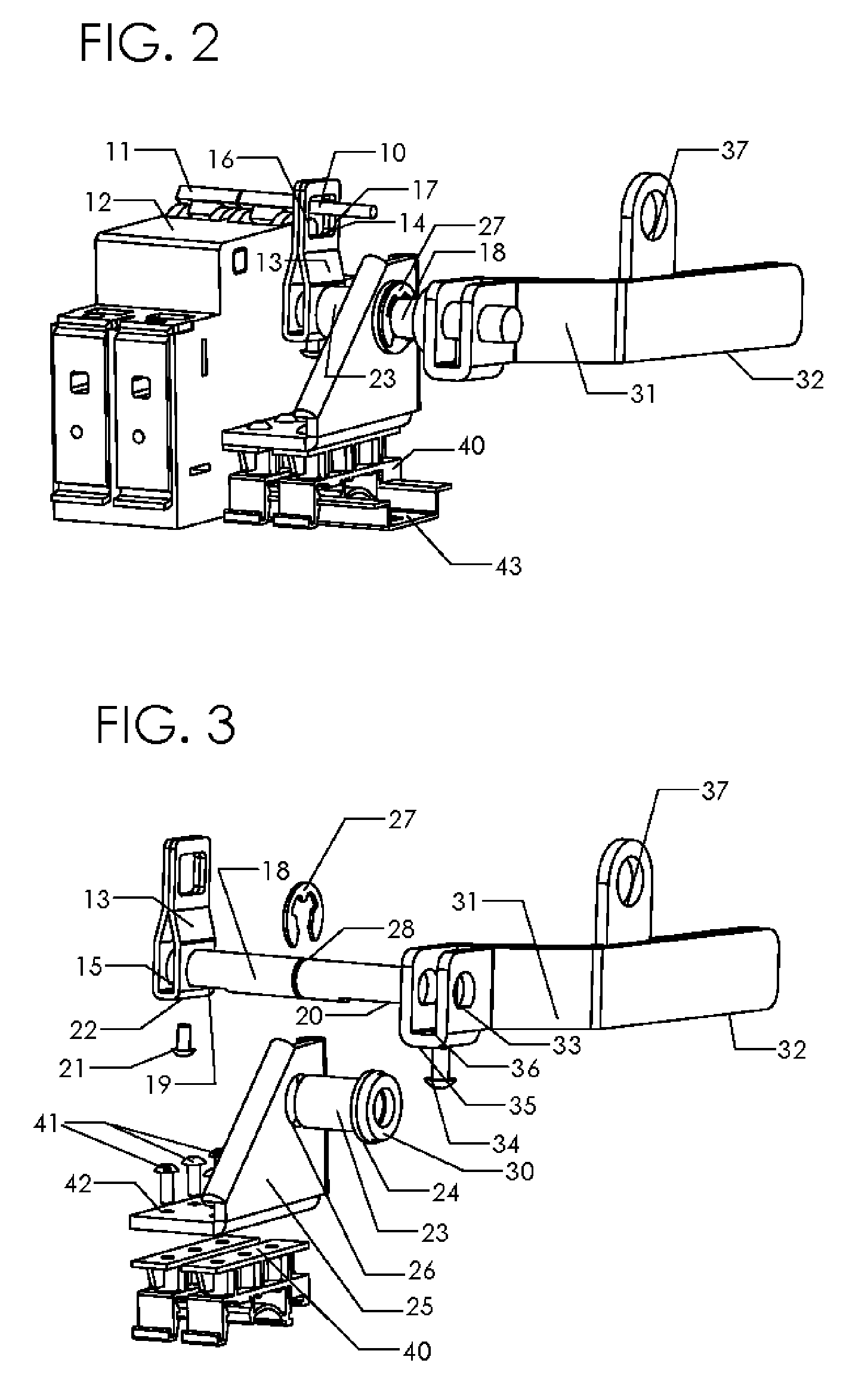
[0030]As illustrated in FIG. 2 of the drawings, extension pin 10 is a cylindrical rod inserted into the hollow chamber of switch arm 11 of the electrical system's circuit breaker 12. Extension pin 10 is similar to pins used by the breaker manufacturer to gang multiple pins together. When one breaker in the gang trips the other breakers in the gang will also trip. The present invention makes new use of existing circuit breaker construction features in extending the gang connection to a mechanism for manual operation of the breaker. An advantage of this method of connecting to the circuit breaker is that the small mass of the connection will not disrupt the proper operation of the circuit breaker. An additional advantage of the connection method of the present invention is that extension pin 10 may be properly sized and shaped so that it will shear before allowing excessive force to be applied to the circuit breaker 12, thus preventing damage. It...


PUM


Abstract

A disconnect mechanism for an electrical system that is integrated with the enclosure of the system, yet includes an external handle for closing and opening the electrical circuit. The invention utilizes the system's circuit breaker to switch the current on or off, eliminating the need for a separate external disconnect. Moving parts are limited to an external actuating handle connected by a shaft to an actuating arm, which has an opening whose inner edges press against a pin connected to the circuit breaker to trigger its movement between the on and off positions. Automatic tripping of the circuit breaker during a system overload moves the external handle to the off position, furnishing visual evidence of the systems working status. A watertight seal maintains the integrity of the electrical system's enclosure.

Description

CROSS-REFERENCE TO RELATED APPLICATIONS[0001]Not ApplicableFEDERALLY SPONSORED RESEARCH[0002]Not ApplicableREFERENCE TO SEQUENCE LISTING[0003]Not ApplicableBACKGROUND OF THE INVENTION[0004]This invention has been devised in the process of developing a photovoltaic inverter which is connected to the utility grid. Some utility companies require equipment which is so connected to include an external disconnect mechanism for easy and rapid disconnection by utility service personnel. In the past, this requirement has been met by adding, to the outside of the photovoltaic inverter main enclosure, a second enclosure containing a switch assembly with an external disconnect lever and terminal lugs which allow wiring connections to the photovoltaic system main enclosure. The disconnect enclosure is costly, bulky, and requires additional assembly at the time of system installation.[0005]Photovoltaic inverters, which are connected to the utility grid, are also required to have circuit protectio...

Claims


Application Information

Patent Timeline
IPC IPC(8): H01H9/20
CPCH01H3/48H01H71/52H01H9/281H01H2003/0286
Inventor WILEY, BRIAN THOMASCHAN, PALVIN CHEE LEONG
Owner WILEY ELECTRONICS
Learn More