Zoom lens and imaging device

a zoom lens and imaging device technology, applied in the field of zoom lenses and imaging devices, can solve the problems of inability to collapse the lens in a satisfactorily small size, inability to form inability to meet the needs of the zoom lens in a short length, so as to improve the focusing ability of the zoom lens, the effect of low cost and compact construction

Inactive Publication Date: 2006-01-31
SONY CORP
View PDF3 Cites 11 Cited by
  • Summary
  • Abstract
  • Description
  • Claims
  • Application Information

AI Technical Summary

Benefits of technology

[0011]Inequality (1) defines the interval between the first and the second lens group, Inequality (2) defines the total length of the second lens group, and Inequality (3) defines the optical length of the zoom lens. The zoom lens according to the present invention has compact construction and can be manufactured at a low cost.

Problems solved by technology

Therefore, this lens cannot be collapsed in a satisfactorily small size.
Since the interval between the first lens group and the second lens group is not optimized, there is a difficulty in forming the zoom lens in a short length, and the second lens group is inevitably large because an aperture stop is disposed between the lenses of the second lens group.
The large second lens group makes collapsing the zoom lens in a small size difficult.
Moreover, it is difficult to reduce the cost of this zoom lens.

Method used


Image

  • Zoom lens and imaging device
  • Zoom lens and imaging device
  • Zoom lens and imaging device

Examples


first embodiment

[0038

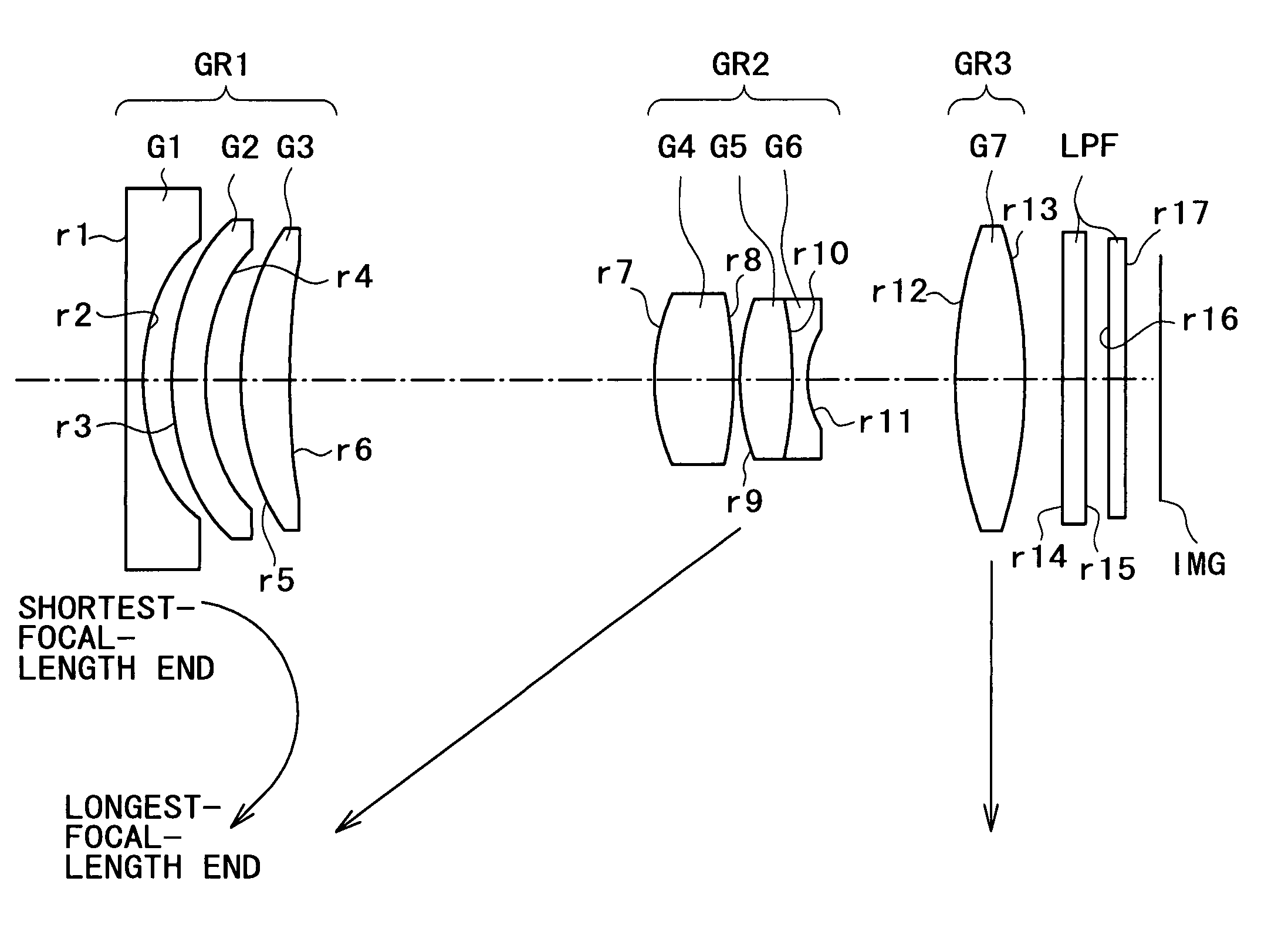
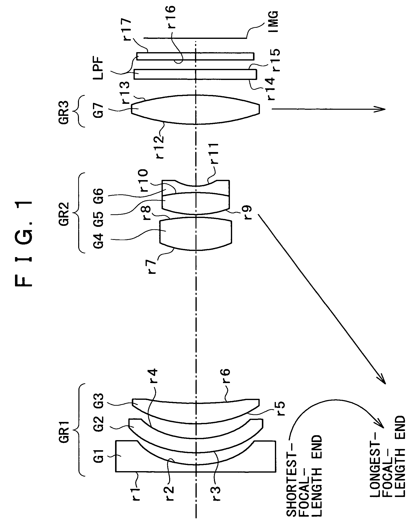
[0039]A zoom lens in a first embodiment according to the present invention shown in FIG. 1 has a negative first lens group GR1, a positive second lens group GR2 and a third lens group GR3 arranged in that order from an object side toward an image side. The first lens group GR1 includes a negative first single lens G1 having a surface having a large curvature and concave toward the image side, a negative second lens G2 having opposite aspheric surfaces and formed of a plastic material, and a positive third lens G3. The second lens group GR2 includes a positive single lens G4 formed of a plastic material, and a compound lens G5 / G6 formed by bonding together a positive single lens G5 and a negative single lens G6. The third lens group GR3 includes a positive single lens G7 having opposite aspheric surfaces and formed of a plastic material.

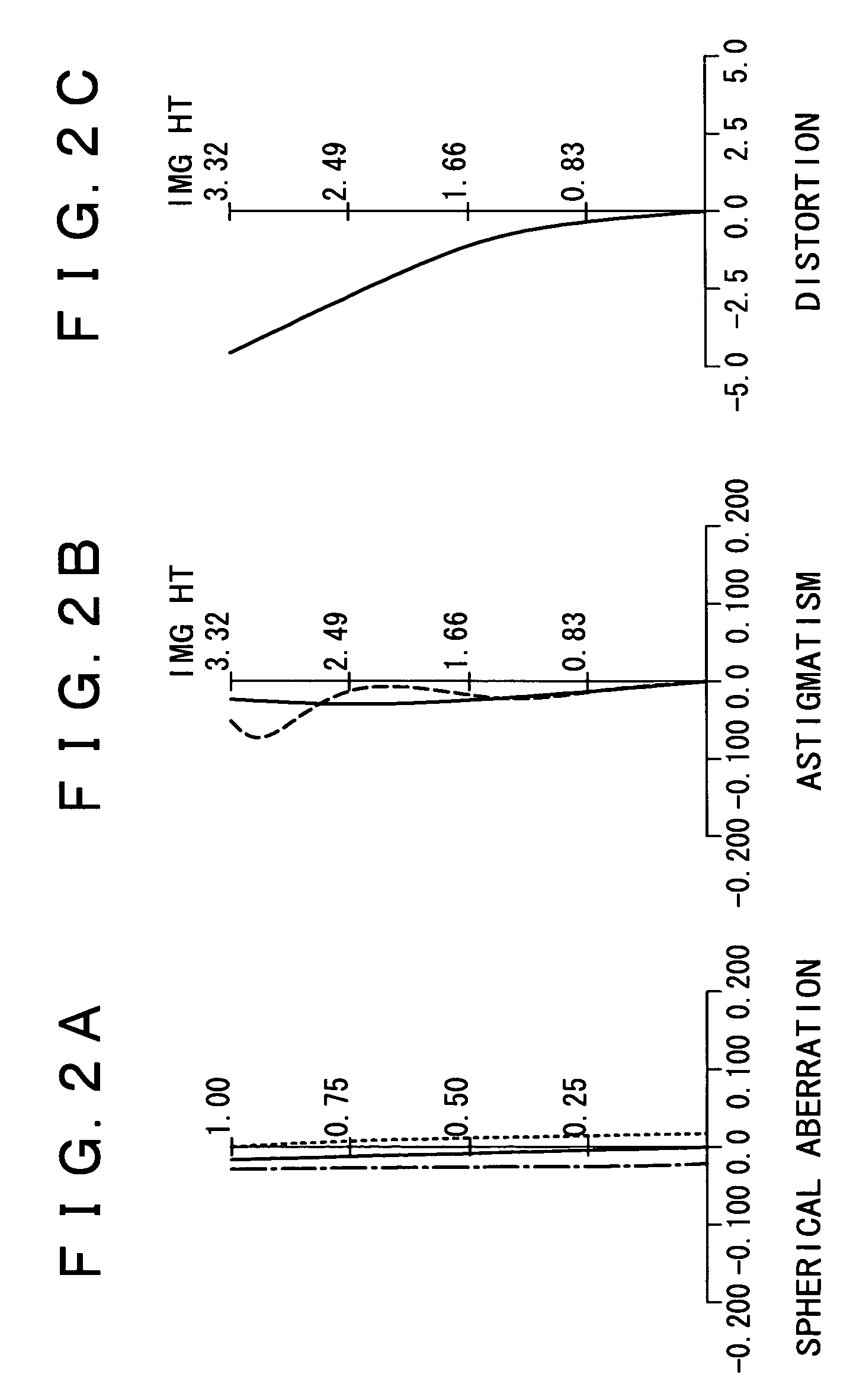
[0040]FIGS. 2A, 2B and 2C show spherical aberration, astigmatism and distortion, respectively, caused by the zoom lens in the first embodiment s...

second embodiment

[0048

[0049]FIG. 5 shows the construction of a zoom lens in a second embodiment according to the present invention. Referring to FIG. 5, the zoom lens has a negative first lens group GR1, a positive second lens group GR2 and a positive third lens group GR3 arranged in that order from an object side toward an image side. The first lens group GR1 includes a negative first single lens G1 having a surface having a large curvature and concave toward the image side, a negative second lens G2 having opposite aspheric surfaces and formed of a plastic material, and a positive third lens G3. The second lens group GR2 includes a compound lens G4 / G5 formed by bonding together a positive single lens G4 and a negative single lens G5, and a positive single lens G6 having opposite aspheric surfaces and formed of a plastic material. The third lens group GR3 includes a positive single lens G7 having opposite aspheric surfaces and formed of a plastic material. The use of the positive single lens G6 hav...

third embodiment

[0054

[0055]FIG. 9 shows the construction of a zoom lens in a third embodiment according to the present invention. Referring to FIG. 9, the zoom lens has a negative first lens group GR1, a positive second lens group GR2 and a positive third lens group GR3 arranged in that order from an object side toward an image side. The first lens group GR1 includes a negative first single lens G1 having a surface having a large curvature and concave toward the image side, a negative second single lens G2 having opposite aspheric surfaces and formed of a plastic material, and a positive third single lens G3. The second lens group GR2 includes a positive single lens G4 having opposite aspheric surfaces and formed of a plastic material, and a compound lens G5 / G6 formed by bonding together a positive single lens G5 and a negative single lens G6. The third lens group GR3 includes a positive single lens G7 having an aspheric surface facing the object side.

[0056]FIGS. 10A, 10B and 10C show spherical abe...


PUM


Abstract

A zoom lens has an optical axis and includes: a negative first lens group capable of being moved for zooming and disposed nearest to the front end; a positive second lens group capable of being moved for zooming, and disposed behind the first lens group; and a positive third lens group disposed behind the second lens group. The zoom lens meets conditions expressed by inequalities:0.02<D12 / fw<0.13  (1)0.5<D2G / fw<0.95  (2)5<TLW / fw<8  (3)where D12 is a minimum distance on the optical axis between a back surface of the first lens group and a front surface of the second lens group, D2G is a distance between front and back surfaces of the second lens group, TLW is optical length of the zoom lens as set in the shortest focal length, and fw is the shortest focal length.

Description

BACKGROUND OF THE INVENTION[0001]1. Field of the Invention[0002]The present invention relates to an inexpensive, small zoom lens having a zoom ratio on the order of three, and an imaging device provided with the zoom lens.[0003]2. Description of the Related Art[0004]Digital still cameras, i.e., imaging devices provided with a solid-state image sensor, have come into wide use in recent years. The wide spread of digital still cameras is accompanied by demand for the further improvement of picture quality. Digital still cameras provided with a solid-state image sensor having a large number of picture elements need a photographic lens, particularly, a zoom lens, having an excellent focusing ability suitable for use in combination with the solid-state image sensor having a large number of picture elements. There has been strong demand for the miniaturization and const reduction of lenses, and the development of inexpensive, small, high-performance zoom lenses.[0005]A zoom lens having a f...

Claims


Application Information

Patent Timeline
Patent Type & Authority Patents(United States)
IPC IPC(8): G02B15/14H04N5/262G02B15/16G02B13/18G02B15/163G02B15/177
CPCG02B15/177G02B15/143507G02B13/009G02B1/041G02B3/0087G02B3/04
Inventor IWASAWA, YOSHITOSUEYOSHI, MASAFUMI
Owner SONY CORP
Why Eureka
Try Eureka