Heat sink

a heat sink and heat dissipation technology, applied in the direction of insulated conductors, instruments, and the like, can solve the problems of shortening adversely affecting the stability of electronic components, and overheating of electronic devices, so as to increase the stability and the service life of electronic components, increase the heat dissipation speed, and improve the service life. the effect of cost effectiveness

Inactive Publication Date: 2006-01-31
GLACIALTECH
View PDF6 Cites 25 Cited by
  • Summary
  • Abstract
  • Description
  • Claims
  • Application Information

AI Technical Summary

Benefits of technology

[0010]Accordingly, in the view of the foregoing, the present inventor makes a detailed study of related art to evaluate and consider, and uses years of accumulated experience in this field, and through several experiments to create a new heat sink. The present invention provides an innovated cost effective heat sink capable of increasing the speed of heat dissipation, and also capable of increasing the stability and the service life of the electronic component.
[0011]According to an aspect of the present invention, a plurality of circularly arranged fins extending from the inner sidewall of the hollow chassis towards the center portion of the hollow chassis with gaps there-between so that gaps between the fins gradually decreases from the inner sidewall of the hollow chassis towards the center of the hollow chassis is provided. A fan is adapted for generating air to increase the amount of air blowing through the wider gaps between the fins to increase the speed of heat dissipation.
[0012]According to another aspect of the present invention, the contact face is adapted for absorbing the heat generated by the operation of the electronic component and the heat pipe is adapted for conducting the heat to uniformly heat the hollow chassis for uniformly transferring the heat to the fins and thereby reduce accumulation of heat on the contact face of the hollow chassis. Therefore, the hollow chassis is capable of uniformly spreading the heat to the plurality of fins. Thus, both the stability and the service life of the electronic component can be effectively increased.

Problems solved by technology

In such a condition, if heat is not being dissipated properly, more and more heat generated by the operation of the electronic components gets accumulated within the electronic device causing over heating of the electronic device.
Over heating may cause ionization and thermal stress to the electronic components and thereby adversely affecting the stability of the electronic components as well as shorten the service life of the electronic components.
Therefore, heat dissipation of the heat generated by the operation of the electronic components cannot be ignored.
The operation of high speed CPU with high efficiency usually generate more heat and because the surface area of the CPU is limited, heat of about 60 to 95° C. may seriously affect the operation of the CPU.
However, in the hollow through channel B1 at the center portion of the substrate B forming the heat pipe is too limited to provide sufficient surface area to efficiently facilitate liquid to gas transformation.
In other words, the coolant in the steam state cannot be frozen promptly and thus the heat cannot be efficiently spread due to poor liquid to gas transformation, causing accumulation of heat on the substrate B and thereby adversely affect the stability and the decreasing service life of the heating object.
However, the fan C generates cool air and blows towards the panel D, the direction of cool air is directed by the smooth spiral fins which easily diverts the cool air away from the bottom of the panel D. Thus, the cool air cannot be blown to the bottom of the panel D to efficiently dissipate the heat there-from.

Method used


Image

  • Heat sink
  • Heat sink
  • Heat sink

Examples


Embodiment Construction

[0021]Reference will be made in detail to the preferred embodiments of the invention, examples of which are illustrated in the accompanying drawings. Wherever possible, the same reference numbers are used in the drawings and the description to refer to the same or like parts.

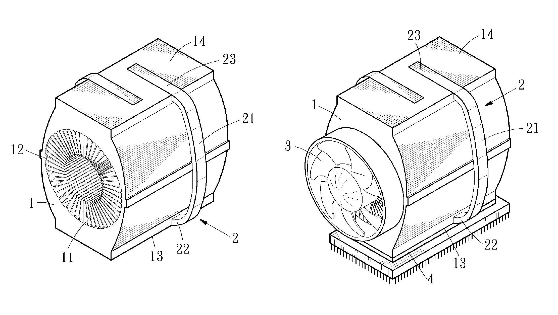
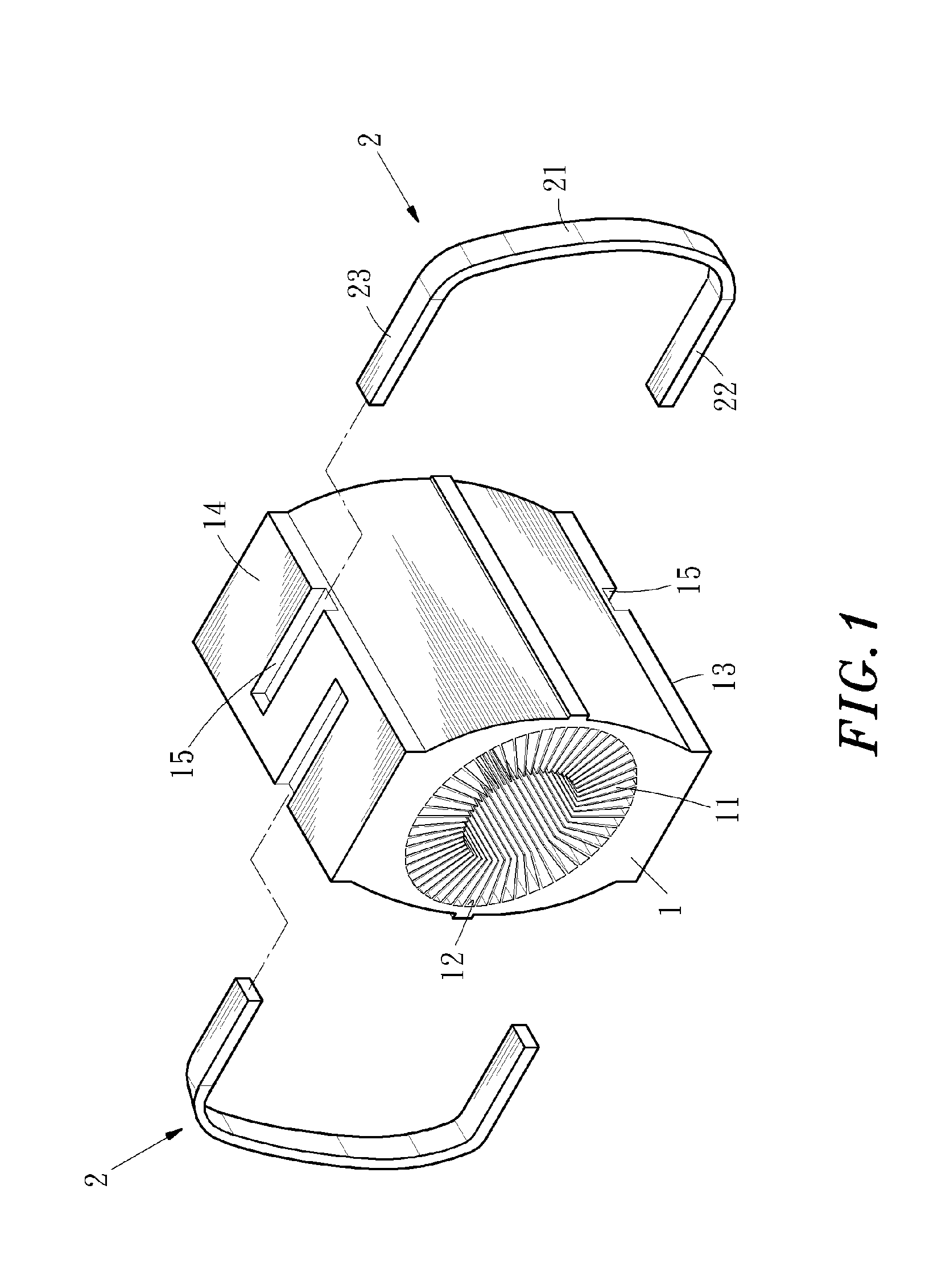
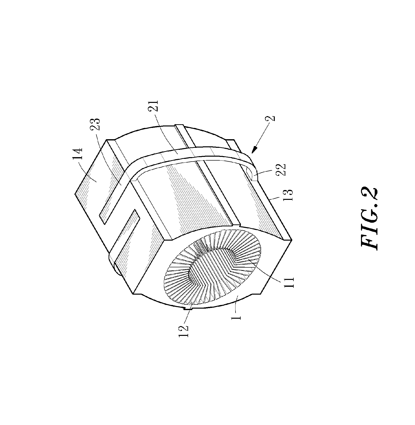
[0022]Referring to FIGS. 1, 2 and 3, the heat sink of the present invention comprises a hollow chassis 1 and a heat pipe 2. The hollow chassis 1 comprises a plurality of circularly arranged fins 11, each fin 11 being separated from the other with a gap. The fins 11 extend from an inner sidewall 12 of the hollow chassis 1 towards the center of the hollow chassis 1 so that the gap between the fins 11 gradually decreases from the inner sidewall 12 towards the center. The hollow chassis 1 comprises a contact face 13 at a bottom portion thereof for attaching to an electronic component 4 and a heat dissipating face 14 at the top portion thereof. The contact face 13 and the heat dissipating face 14 comprise an inlaying...


PUM


Abstract

A heat sink is provided. The heat sink comprises a hollow chassis having a contact face at a bottom portion thereof for attaching to an electronic component and a heat dissipating face at a top portion thereof. A plurality of circularly arranged fins extend from an inner sidewall of the hollow chassis towards a center of the hollow chassis so that gaps between the fins gradually decrease from the inner sidewall of said hollow chassis towards the center of said hollow chassis. At least a heat pipe is positioned between the contact face and the heat dissipating face. At least a fan is positioned at a side of the hollow chassis for generating air to increase an amount of air blowing through wider gaps between said fins to increase the speed of heat dissipation.

Description

[0001]This application claims the priority benefit of Taiwan patent application number 093208561 filed on May 31, 2004.DESCRIPTIONBACKGROUND OF THE INVENTION[0002]1. The Field of the Invention[0003]The present invention relates to a heat sink, and more particularly to a heat sink comprising a plurality circularly arranged fins extending from the inner sidewall of a hollow chassis towards the center of the hollow chassis with gaps there-between so that the width of the gaps gradually decreases from the inner sidewall to the center of the hollow chassis and a fan is used to generate air to increase the amount of air blowing through the wider gaps between the fins in order to increase the speed of heat dissipation.[0004]2. Description of Related Art[0005]The highly developed technology has made it possible to fabricate miniaturized electronic components for increasing the density of the electronic device and the operation efficiency thereof. In such a condition, if heat is not being di...

Claims


Application Information

Patent Timeline
Patent Type & Authority Patents(United States)
IPC IPC(8): H05K7/20F28D21/00G06F1/20H01L23/40H01L23/467
CPCG06F1/20H01L23/4093H01L23/467H01L2924/0002H01L2924/00
Inventor WANG, YING-CHIHKAO, YONG-CHANGTSAI, CHI-NAN
Owner GLACIALTECH
Why Eureka
Try Eureka