Transmitting apparatus and gain compensating method

a technology of transmission apparatus and gain compensation, which is applied in the direction of multiplex communication, power management, system details of baseband system, etc., can solve the problems of increasing calculation amount, difficult to accurately compensate gain compensation, and deteriorating gain, and achieves small calculation amount and high accuracy

Inactive Publication Date: 2006-01-31
PANASONIC CORP
View PDF17 Cites 0 Cited by
  • Summary
  • Abstract
  • Description
  • Claims
  • Application Information

AI Technical Summary

Benefits of technology

[0011]It is an object of the present invention to provide a transmission apparatus and gain compensation

Problems solved by technology

A transmit amplifier has a problem that the gain deteriorates due to changes in temperature and changes with time.
However, since the conventional transmission apparatus needs to average amplitude values of the amplified transmit output data and amplitude values of the code-multiplexed transmit data accumulated during a predetermined period of time, the apparatus has a pr

Method used


Image

  • Transmitting apparatus and gain compensating method
  • Transmitting apparatus and gain compensating method
  • Transmitting apparatus and gain compensating method

Examples


Embodiment Construction

[0017]The inventor of the present invention focused on the fact that in the case of a TDD (Time Division Duplex) system, a signal is not transmitted during a time a signal is received, it is not necessary to transmit a signal used for the gain compensation to a communication partner, and that the constant transmit power of such a signal eliminates the necessity of averaging, and carried out the present invention.

[0018]Namely, it is a gist of the present invention to add redundant data with constant transmit power to transmit data using a time a signal is not transmitted, and to perform the gain compensation based on a difference value between an amplitude value of amplified redundant data and a target amplitude value.

[0019]An embodiment of the present invention will be described below with reference to accompanying drawings.

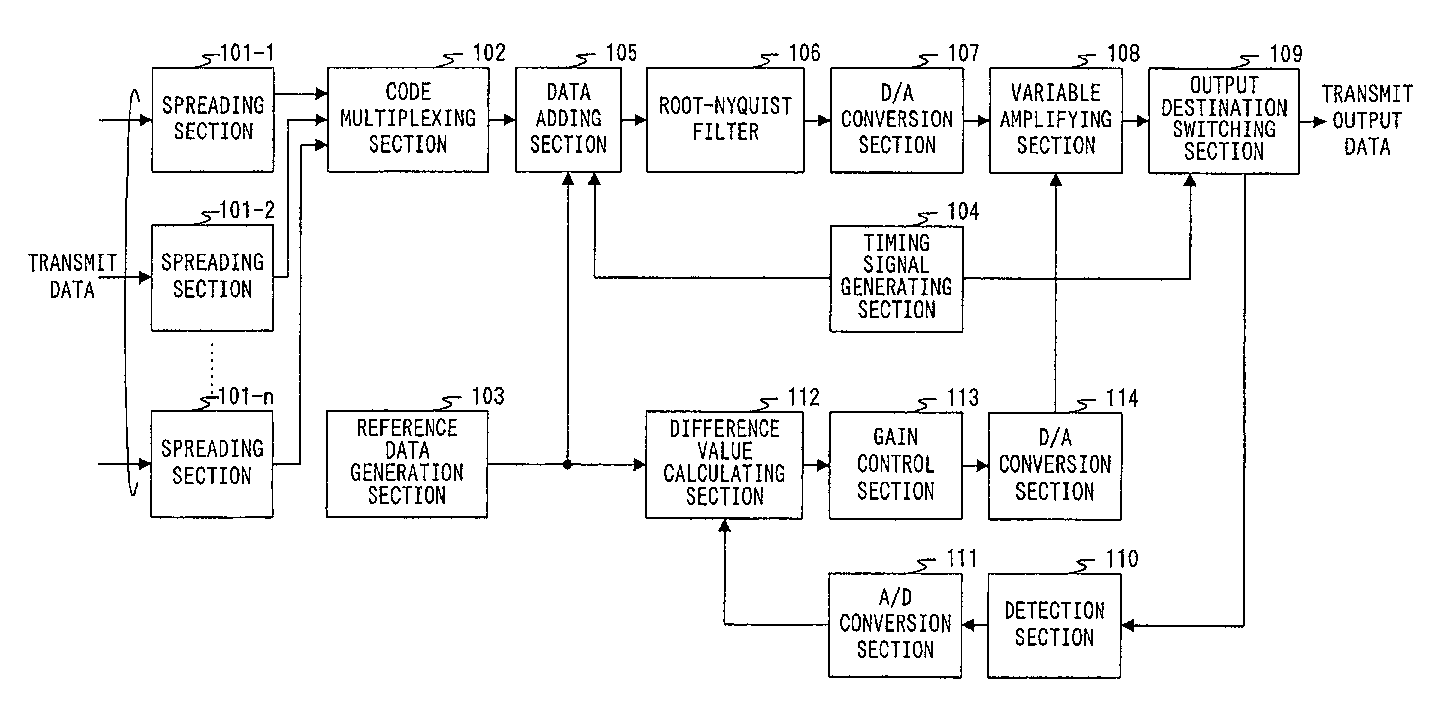
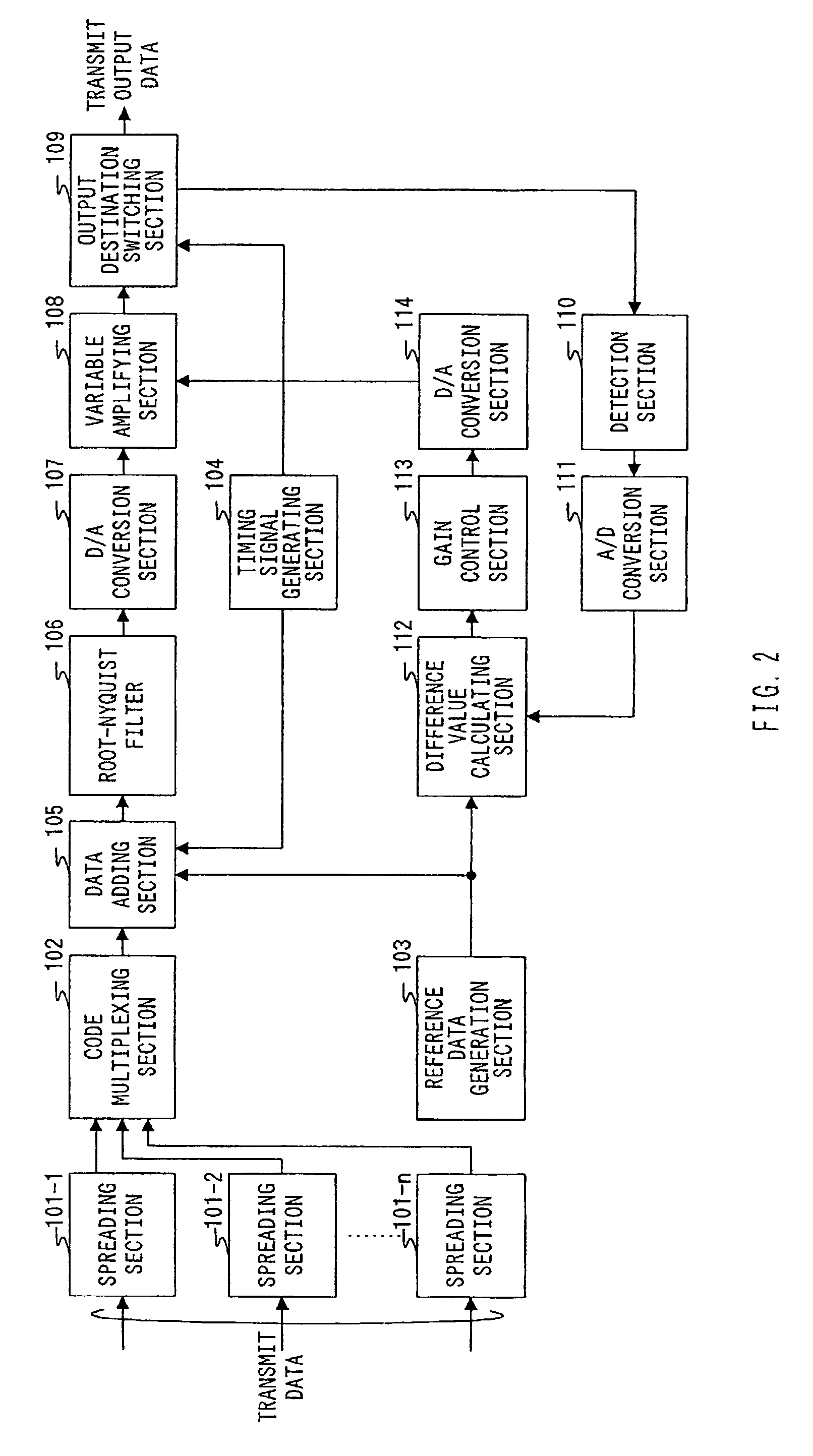
[0020]FIG. 2 is a block diagram illustrating a configuration of a transmission apparatus according to one embodiment of the present invention.

[0021]In the transm...


PUM


Abstract

A code multiplexer multiplexes spread data output from a spreader to generate code-multiplexed data. A reference data generator generates redundant data with constant power and with no information contained therein. A data adder adds the redundant data to the code-multiplexed data. A variable amplifier variably amplifies the transmit power of the code-multiplexed data and the redundant data to obtain transmit output data. A difference value calculator calculates a difference value between a target amplitude value and the amplitude of the amplified redundant data. A gain controller generates, based on the difference value, a gain control signal to control the gain of the variable amplifier. It is thereby possible to perform gain compensation with a small calculation amount and with high accuracy.

Description

[0001]This application is a 371 of PCT / JP01 / 01805 Mar. 8, 2001.TECHNICAL FIELD[0002]The present invention relates to a transmission apparatus and gain compensation method for performing a compensation of an amplification gain of transmit power in a CDMA (Code Division Multiple Access) radio communication system.BACKGROUND ART[0003]A transmit amplifier has a problem that the gain deteriorates due to changes in temperature and changes with time. The characteristic deterioration caused by the changes in temperature is improved by installing a temperature-dependent characteristic changing element on a circuit such as a thermistor as a representative example.[0004]Further, in order to cope with the changes with time, the amplification gain of the transmit power is compensated using a variable gain amplifier or variable attenuator installed on a signal processing line.[0005]As disclosed in Japanese Laid-Open Patent Publication HEI11-27233, a conventional transmission apparatus uses as a r...

Claims


Application Information

Patent Timeline
IPC IPC(8): H04B1/69H04J13/02H03G3/00H04B1/707H04B7/005H04J13/00
CPCH03G3/001H03G3/005H04B1/707H04W52/52H04J13/00H04W52/44H04B2201/709709H04B2201/70706
Inventor CHINDA, YUSUKEHIRAMATSU, KATSUHIKO
Owner PANASONIC CORP
Why Eureka
Try Eureka