Examination system, image processing apparatus and method, medium, and X-ray photographic system

a technology of x-ray and image processing equipment, applied in the field of examination system, image processing equipment and method, medium, x-ray photographic system, can solve the problems of low rate at which x-rays may be taken, inability to efficiently perform proper positioning, and above-described problems, etc., to achieve convenient operation, easy to understand, and easy to determine

Inactive Publication Date: 2006-01-31
CANON KK
View PDF6 Cites 14 Cited by
  • Summary
  • Abstract
  • Description
  • Claims
  • Application Information

AI Technical Summary

Benefits of technology

[0018]Another object of the present invention is to provide an apparatus capable of taking X-ray photographs using a plurality of photographic methods with easy operation, which are easy to understand for both the requestor (for example, a doctor) and the operator (for example, a technician).
[0019]Another object of the present invention is to provide an apparatus capable of taking a large number of X-ray photographs, in which it is easy to determine the photographs which are yet to be taken in the photographing order, the portion currently being photographed, and the portions which have already been photographed.
[0030]With such a construction, it is possible to efficiently take X-ray photographs in a sequence desired by the photographer (technician) regardless of the sequence in the requested photographic order.

Problems solved by technology

However, since the X-ray photography of the “cervical vertebra, foramen” for the second photography is performed by the photographic apparatus with the patient in a recumbent position, the proper positioning of the patient is time-consuming, causing problems in that this is burdensome and the rate at which X-rays may be taken is low.
Even in this case, the above-described problems remain.
In a manner as described above in the first X-ray photography situation, there is a problem in that proper positioning cannot be performed efficiently when the predetermined photographic sequence is inconvenient for the technician; therefore, the photographing efficiency is decreased, and the burden on the patient is substantial.
In the second X-ray photography situation, effort is subsequently required to rearrange the sequence of the image films into that which the doctor wishes to see, and this is also inconvenient.
Another problem is that there is no effective means to confirm the order of the part currently being X-rayed and to confirm which part is photographed last.
In addition, a problem arises in that when an X-ray must be retaken, this retake must be performed before the next part is X-rayed.
As described above, there are problems in that when X-ray photography is to be performed in a requested sequence, the photographing efficiency may be decreased, and in that the rearrangement of the sequence to that in which the doctor will view the images after the X-ray photographs are taken is very complicated.
In addition, problems occur in that it cannot be confirmed which part in the photographing order is currently being photographed, and in that when the image is blurred, retake cannot be performed quickly.
Such problems occur not only in the above-described examination apparatus, but also in other photography, for example, in a case in which images from a consumer digital camera are printed out.

Method used


Image

  • Examination system, image processing apparatus and method, medium, and X-ray photographic system
  • Examination system, image processing apparatus and method, medium, and X-ray photographic system
  • Examination system, image processing apparatus and method, medium, and X-ray photographic system

Examples


first embodiment

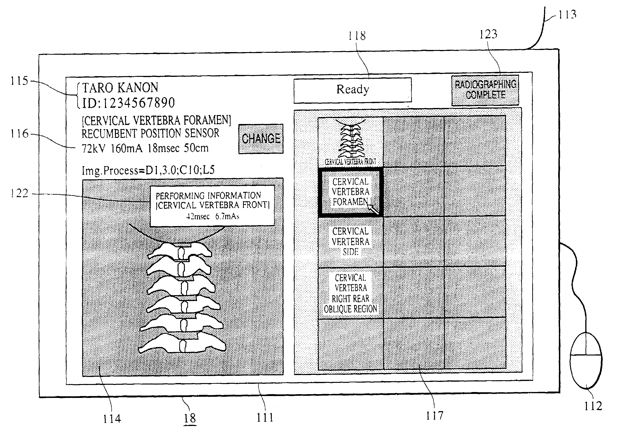
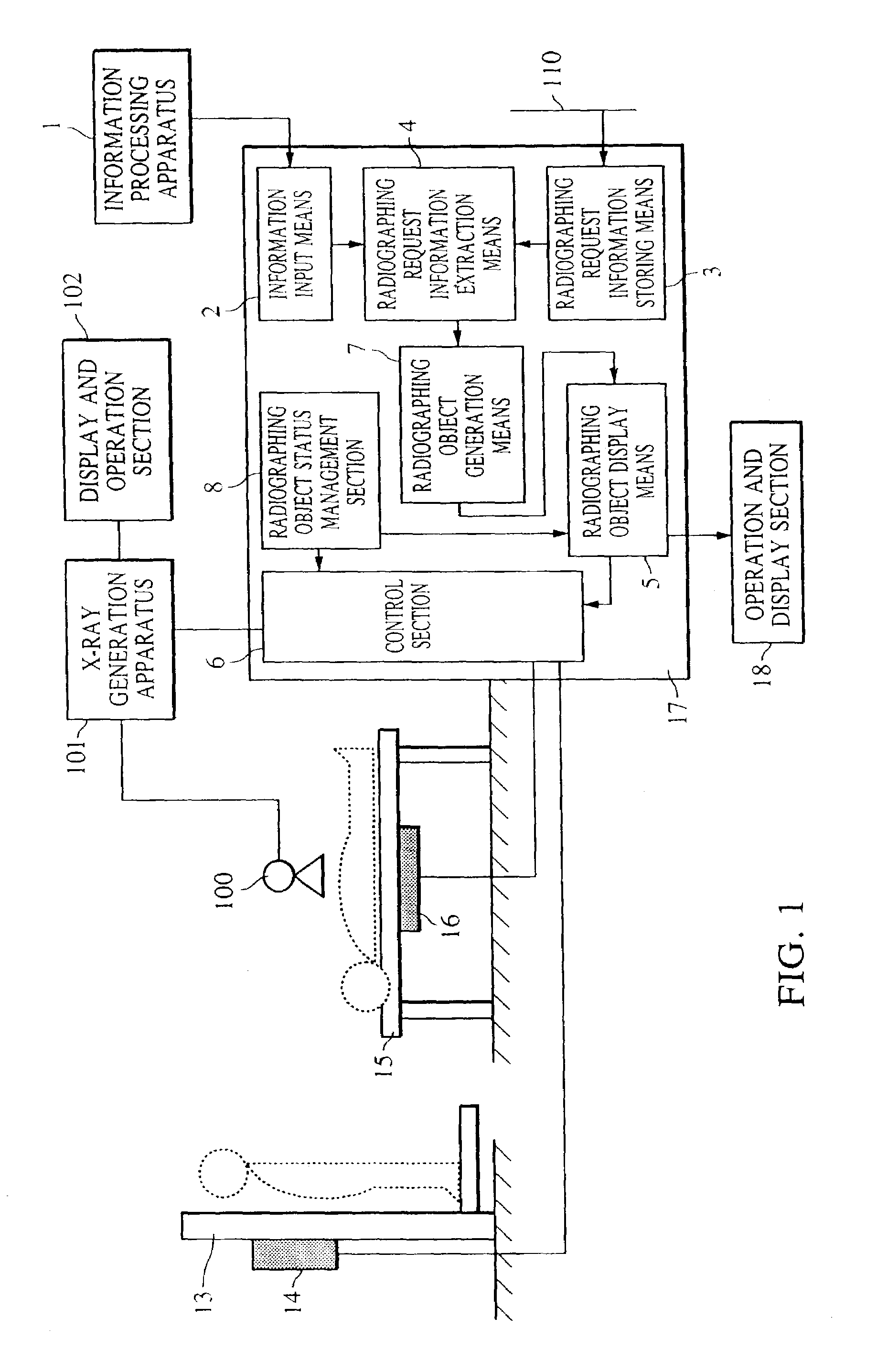
[0047]FIG. 1 shows the system configuration of an X-ray photographic system according to a first embodiment of the present invention.

[0048]Components in FIG. 1 which are the same as those of FIG. 12 described earlier designate the same. This X-ray photographic system (radiography system) comprises a standing position sensor unit 13, a recumbent position sensor unit 15, an X-ray generation apparatus 101, an operation and display section 102 of the X-ray generation apparatus, a control section 17 of an X-ray photographic (radiography) apparatus, an operation and display 18 of the X-ray photographic apparatus, and an information processing apparatus 1.

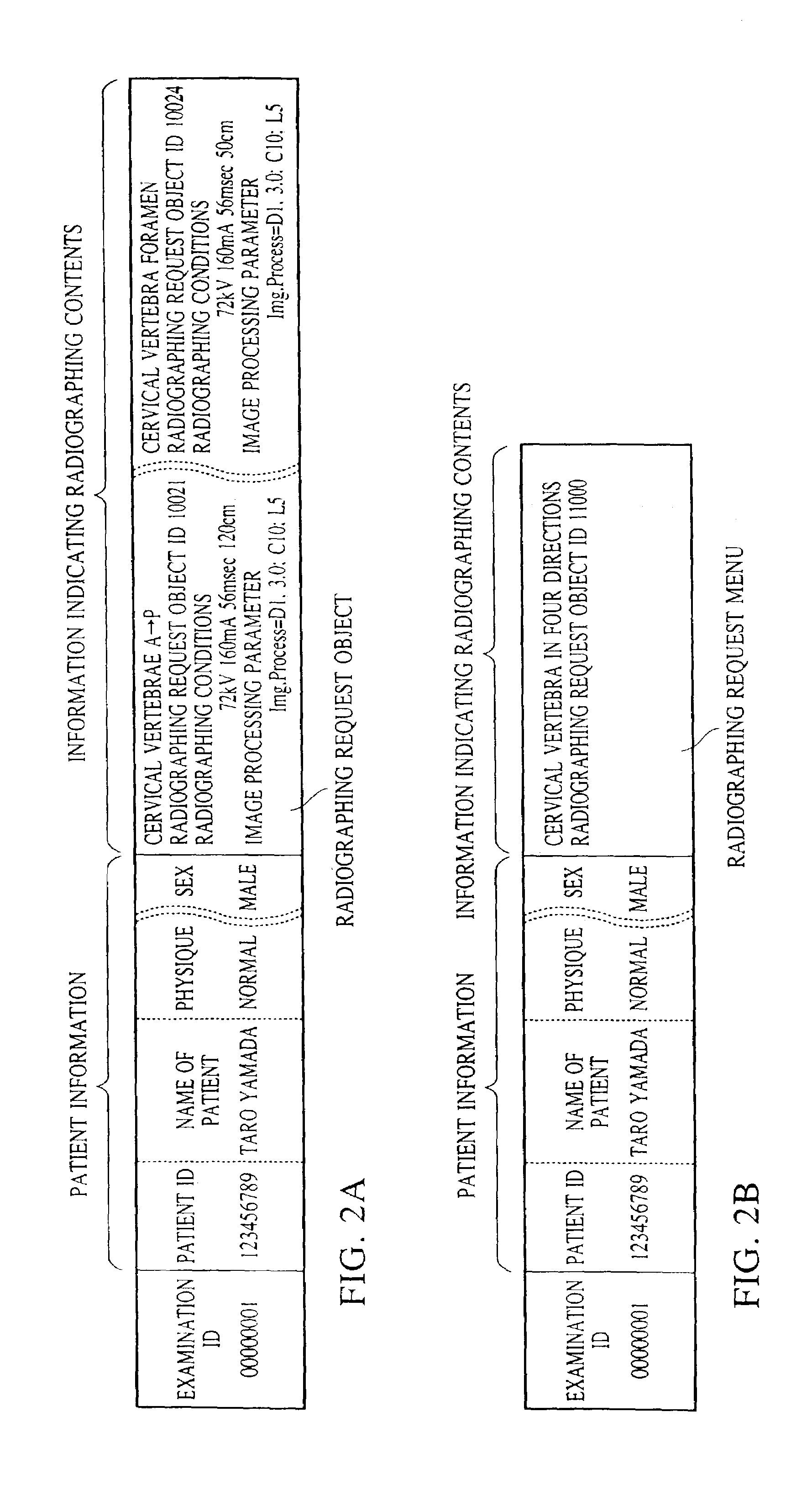
[0049]In FIG. 1, reference numeral 1 denotes an information processing apparatus for reading the contents of magnetic stripes of a magnetic card, and reference numeral 2 denotes information input means for inputting an examination ID read by the information processing apparatus 1. Reference numeral 3 denotes photographic request informati...

second embodiment

[0062]The sequence of the photographic request objects is fixed by a doctor and a technician and by implementation after being put into practical use in particular medical facilities. Therefore, it is effective that a correspondence table is created in advance and the photographic order is converted in accordance with the table. This table is referred to when photographic request information is extracted by the photographic request information extraction means 4 in FIG. 1 and when photographs are transferred to the image server and the imager after the photographs are taken. Then, the sequence of the photographic request objects is automatically converted on the basis of the request information and the status of a technician switch 120 and a transfer destination switch 121.

[0063]FIG. 10 shows an example of this conversion table. In this case, the operation and display section 18 is as shown in FIG. 8. Reference numeral 120 denotes a technician switch, which is a key for identifying ...


PUM


Abstract

A system for handling examination of an object includes an input for inputting examination request information, including a plurality of examination methods, for an object, and a performing device for performing examinations for the plurality of examination methods in an arbitrary order and obtaining results therefrom. In addition, an output outputs the results of the plurality of examination methods in a determined order regardless of an order in which the performing device has performed examinations for the plurality of examination methods.

Description

CROSS-REFERENCE TO RELATED APPLICATION[0001]This application is a continuation-in-part of application Ser. No. 10 / 235,660, filed Sep. 6, 2002 now abn., which is a divisional of application Ser. No. 09 / 407,086, filed Sep. 28, 1999 U.S. Pat. No. 6,501,827.BACKGROUND OF THE INVENTION[0002]1. Field of the Invention[0003]The present invention relates to an examination system suitable for an X-ray photographic system, for example, for taking an order from a doctor for the taking of an X-ray photograph (radiograph) and for performing X-ray photography (radiography), to an image processing apparatus and method, and to a medium therefor.[0004]2. Description of the Related Art[0005]An “X-ray photographic apparatus” refers to an apparatus for detecting X-rays, which have been transmitted through a patient, to form an image. This image is formed by representing differences in the transmittance of each type of the tissue structure in the body of the patient and the thickness thereof as a photogr...

Claims


Application Information

Patent Timeline
Patent Type & Authority Patents(United States)
IPC IPC(8): H05G1/64G16H30/20G16H40/63
CPCG06F19/3487G06F19/321G06F19/3418G16H15/00G16H40/63G16H30/20
Inventor TAKASAWA, TORU
Owner CANON KK
Why Eureka
Try Eureka