Method for controlling an industrial processing machine

a three-dimensional path and industrial processing technology, applied in the direction of electric programme control, program control, instruments, etc., can solve the problem that the method of motion control is not capable of fully and continuously describing a freeform surface for turning, restricts the use of spline interpolation for controlling the path of numerically controlled machines or robots, and requires a large memory space. the effect of increasing the rotation speed

Inactive Publication Date: 2006-01-31
SIEMENS AG
View PDF15 Cites 4 Cited by
  • Summary
  • Abstract
  • Description
  • Claims
  • Application Information

AI Technical Summary

Benefits of technology

[0016]The method of the invention advantageously improves the performance of a processing machine. For example, turning machines can be operated at a higher rotation speed. The method can advantageously be executed using standard components of numerical controllers and allows a more universal program definition. Freeform contours can be easily generated without requiring additional hardware components. In addition, application-specific programs using position tables can also be eliminated.

Problems solved by technology

This restricts the use of spline interpolations for controlling the path of numerically controlled machines or robots.
The tables are quite large and require a large memory space.
Moreover, this method for motion control is not capable of completely and continuously describing a freeform surface for turning, because the tables are constructed two-dimensionally and can only be changed in a discrete fashion.

Method used


Image

  • Method for controlling an industrial processing machine
  • Method for controlling an industrial processing machine
  • Method for controlling an industrial processing machine

Examples


Embodiment Construction

[0030]Throughout all the Figures, same or corresponding elements are generally indicated by same reference numerals. These depicted embodiments are to be understood as illustrative of the invention and not as limiting in any way.

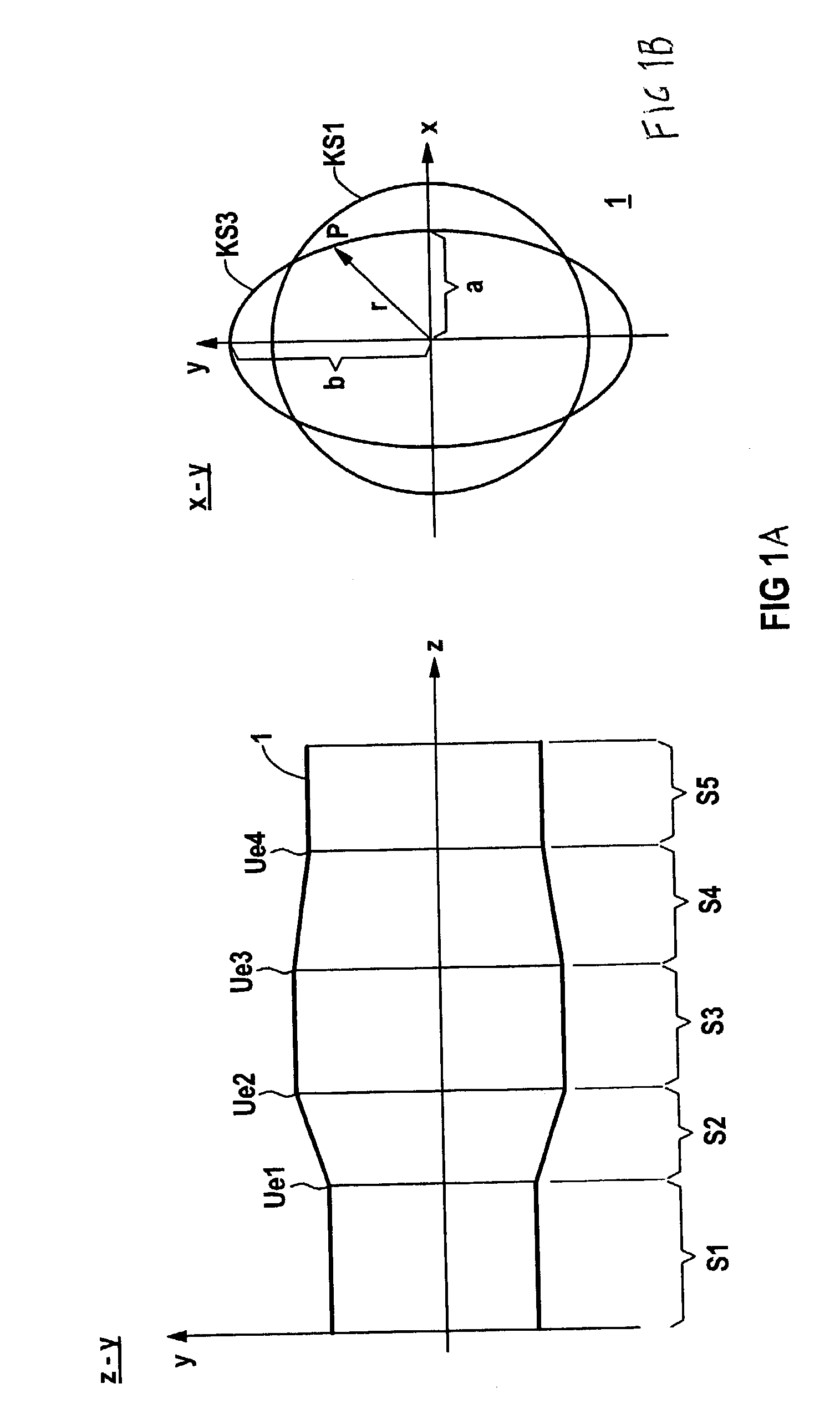
[0031]Turning now to the drawing, and in particular to FIGS. 1A and 1B, there is shown an example for turning sinusoidal contours. A body 1, for example, a workpiece, can be represented in a Cartesian coordinate system having x-, y-and z-axes. In FIG. 1A, the body 1 is illustrated in a longitudinal cross section in a z-y coordinate system, whereas FIG. 1B shows the body 1 in a transverse cross section taken along Ue1 (KS1) and Ue3 (KS3), respectively, in an x-y coordinate system. The body 1, i.e. the useful element, can be subdivided into several sectors S1, S2, S3, S4 and S5, wherein Ue1, Ue2, Ue3 and Ue4 indicate transition points between the sectors. This configuration of the body 1 is depicted in the diagram represented in the y-z coordinate system (FIG....


PUM


Abstract

A method and system for describing a three-dimensional path of an industrial processing machine, such as a machine tool, a robot and the like, is disclosed. According to the disclosed method and system, the path is described by a curve that includes at least one interpolation, wherein at least one interpolation parameter is a function of an angle along the three-dimensional path.

Description

CROSS-REFERENCES TO RELATED APPLICATIONS[0001]This application claims the priority of German Patent application, Ser. No. 102 24 755.2, filed Jun. 4, 2002, pursuant to 35 U.S.C. 119(a)–(d), the disclosure of which is incorporated herein by reference.BACKGROUND OF THE INVENTION[0002]The invention relates to a method for describing the three-dimensional path of an industrial processing machine, such as a machine tool, a robot and the like.[0003]Published European patent specification EP 04 17 337 A1 describes a method for controlling a numerically controlled machine or a robot using a spline interpolation. The axes parameters (x, y) are hereby defined as functions of a path parameter (s). The velocity along the path is controlled by expanding the paths of the functions or by sampling the paths with different step lengths. Alternatively, the support points for the spines can be varied as a function of the path parameters to reflect a desired velocity profile.[0004]Disadvantageously, wh...

Claims


Application Information

Patent Timeline
Patent Type & Authority Patents(United States)
IPC IPC(8): G06F19/00G05B19/4103
CPCG05B19/4103G05B2219/36202G05B2219/34135
Inventor UHLICH, ANDREAS
Owner SIEMENS AG
Why Eureka
Try Eureka