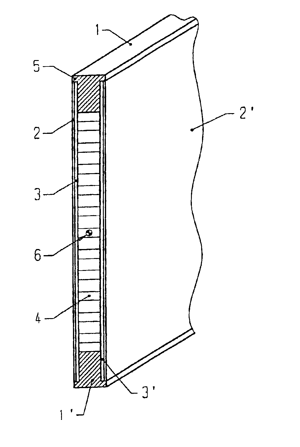
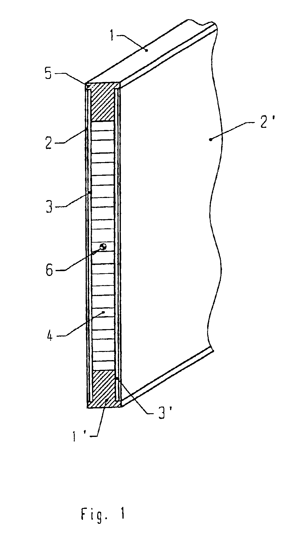
[0013]Construction of the heddle bar of the invention will therefore be very simple. The plastic profiled pieces are arranged around a rectangular core along the edges thereof, preferably made of
honeycomb-shaped material, whereby the profiled pieces are reinforced with unidirectional fibers oriented in the longitudinal direction of the heddle bar.
Carbon fibers with a high modulus of elasticity are used for this purpose. On the wide side of the three parts, there are thin formed bodies applied, preferably woven material or a fibrous web, which are first soaked with an
adhesive. On the outer side, thin pieces of sheet
metal are applied to the fibrous structures that are soaked with an
adhesive. All parts are finally glued together in one operational step at a high temperature to achieve the necessary stability.
[0014]Possibilities of a large variety are achieved with this inventive embodiment relative to the adjustment of stiffness (rigidity) of the support bar to specific requirements. Thus, the cross-section of the
fiber-reinforced profiled piece can be changed without having to change the outer dimensions of the support bar. The pieces of sheet
metal on the side, which are preferably made of steel or aluminum, have the great
advantage of isotropic material characteristics. There can be achieved the same effect in stability with one single, thin, and therefore, light sheet
metal piece, as with a fibrous structure, which would have to be made of several
layers with fibers crossing each other at various angles. Fibrous structures have in fact very anisotropic stability characteristics. In
spite of its low individual weight, such a fibrous structure becomes heavier than even a comparable sheet metal piece made of steel when at least a semi-isotropic stability behavior is required. Such behavior is necessary for the side pieces, which are exposed to stress (loads) from different directions.
[0015]In one preferred embodiment, at least one of the carbon-fiber reinforced plastic profiled pieces is designed having two small projections at the narrow side. These projections serve as
positioning aids during
assembly of the side components and they make considerably easier the
assembly of the parts that have not been glued together yet.
[0016]In another preferred embodiment, the fibrous structures are made of glass fibers or aramide fibers whereby the fibrous structures serve as support for the
adhesive. It is insignificant whether a fibrous web or woven material is employed. However, it is important that the fibrous structure comprise a non-conductive material. This is optimally achieved with the use of glass fibers. This fibrous structure serves not only as support for the adhesive, but it must form at the same time an insulating layer between the
carbon fibers and the sheet metal sides to prevent
corrosion effects. Since
carbon fibers are more noble than iron, damage by
corrosion could develop at the broad surface contact of the
carbon fibers with the sheet metal pieces made of steel on the sides.
[0019]However, inventively advantageous is the employment of materials having isotropic behavior and anisotropic behavior geometrically arranged at locations where specific characteristics of the respective material may be used at best. That means therefore: doing without the heddle mounting rail as supporting element, having the arrangement of fiber-reinforced plastic profiled pieces with their highly anisitropic stability characteristics located far away from the center of gravity of the support bar, and having the arrangement of sheet metal with its great isotropic stability characteristics near the center of gravity of the support bar for the purpose of a mechanical connection of the fiber-reinforced plastic profiled pieces with the
solid support bar. Important is furthermore the use of a light but sturdy core. An even surface of the side pieces is assured, even at
high stress, by gluing the core to the side pieces. The side pieces can thereby fulfill the objective, even by being thin, to durably attach the fiber-reinforced plastic profiled pieces to form the
solid support bar. Finally, an
advantage is also the use of a wide-spread
fiber structure as adhesive carrier and as an insulating element, according to the invention.

