
Resin-coated metal sheet for container

a metal sheet and resin coating technology, applied in the direction of synthetic resin layered products, rigid containers, packaging, etc., can solve the problems of long treatment time, large solvent discharge, and the technique used for painting, and achieve good content releasability

Active Publication Date: 2020-03-03
JFE STEEL CORP
View PDF37 Cites 0 Cited by
  • Summary
  • Abstract
  • Description
  • Claims
  • Application Information

AI Technical Summary

Benefits of technology

[0027]According to the present disclosure, a resin-coated metal sheet for containers that exhibits good content releasability from various contents is obtained. The resin-coated metal sheet for containers of the present disclosure can stably meet various properties required of food can materials.

Problems solved by technology

However, the technique used for painting has problems such as its complicated baking process, a long treatment time, and discharge of a large amount of solvents.
A problem with the use of a resin-coated metal sheet for a food can container is that, since the contents of the container strongly stick to the inner surface of the container when the contents are taken out of the container, the contents are not easily taken out.
This problem is closely related to consumer purchasing intention and is a very important issue in terms of ensuring the consumer purchasing intention.
Nevertheless, there are very few studies on improvement in the ease of releasing contents from the conventional resin-coated metal sheets (their content releasability).
When a resin coating (laminated coating) is applied to the outer surface of a can by thermal-fusion bonding of an ordinary polyester resin film, a problem arises in that the polyester resin film is discolored when subjected to high-temperature sterilization treatment such as retort treatment.

Method used


Image

  • Resin-coated metal sheet for container
  • Resin-coated metal sheet for container

Examples


example 1

[0090]Exemplary examples of the present disclosure will next be described.

(Method for Producing Metal Sheet)

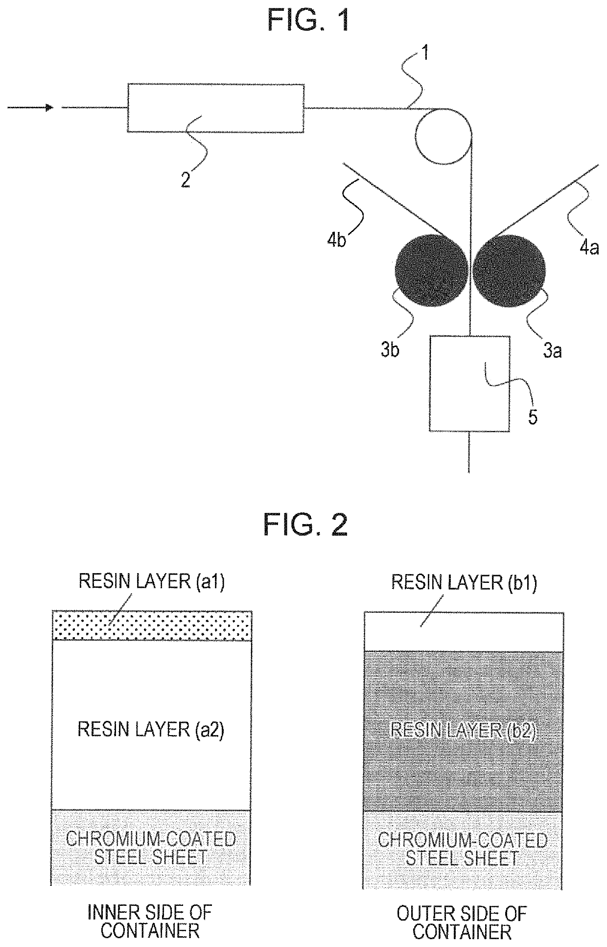
[0091]A strip-shaped steel sheet subjected to cold rolling, annealing, and temper rolling and having a thickness of 0.18 mm×a width of 977 mm was subjected to degreasing, pickling, and then chromium plating, and a chromium-coated steel sheet (TFS) was thereby produced. The chromium plating was performed in a chromium plating bath containing CrO3, F− and SO42−. After intermediate rinsing was performed, electrolysis was performed using a chemical conversion treatment solution containing CrO3 and F−. In this case, the electrolysis conditions (such as current density and the quantity of electricity) were controlled such that the coating weight of metal chromium and the coating weight of chromium hydroxide were 120 mg / m2 and 15 mg / m2, respectively, in terms of chromium.

(Method for Producing Film for Resin Coating on Inner Side of Container)

[0092]A resin composition (a raw material ...


PUM

PropertyMeasurementUnit
thicknessaaaaaaaaaa
thicknessaaaaaaaaaa
thicknessaaaaaaaaaa

Abstract

A resin-coated metal sheet for containers that has excellent content releasability is provided. The resin-coated metal sheet includes a resin layer (A) and a resin layer (B). The resin layer (A) has a multilayer structure and is disposed on a side which, after the metal sheet is formed into a container, becomes the inner side of the container. The resin layer (B) is disposed on a side that becomes the outer side of the container. The resin layer (A) contains polyester as a main component and includes an uppermost resin layer (a1). A Raman band intensity ratio (I2968 / I3085) on the surface of the resin layer (a1) is 0.6 to 0.9. The resin layer (B) includes polyester (I) composed mainly of polyethylene terephthalate and a polyester (II) composed mainly of polybutylene terephthalate. A Raman band intensity ratio on the surface of the resin layer (B) is 0.8 to 1.0.

Description

TECHNICAL FIELD[0001]The present disclosure relates to a resin-coated metal sheet for containers that is used for can bodies, lids, etc. of food can containers.BACKGROUND ART[0002]Metal sheets such as tin-free steel (TFS) sheets and aluminum sheets that are used as metal can materials for food can containers are conventionally painted for the purpose of improving corrosion resistance, durability, weather resistance, etc. However, the technique used for painting has problems such as its complicated baking process, a long treatment time, and discharge of a large amount of solvents. To solve these problems, resin-coated metal sheets prepared by laminating thermoplastic resin films onto heated metal sheets have been developed as substitutes for the painted metal sheets and are currently used widely for industrial purposes, mainly for beverage can materials.[0003]A problem with the use of a resin-coated metal sheet for a food can container is that, since the contents of the container str...

Claims


Application Information

Patent Timeline
Patent Type & Authority Patents(United States)
IPC IPC(8): B32B15/09B29C55/12B32B15/18B32B37/20B65D25/14B32B27/18B32B27/36B65D1/16C21D9/46C25D3/10B29C48/00B29C48/21B32B27/08B32B7/02C08L91/06B65D1/12B32B7/023B32B15/20C08L67/03B32B15/08B29K67/00
CPCB32B27/18B32B15/09B32B15/18C25D3/10B65D25/14B32B37/203B32B27/36C21D9/46B65D1/165B32B27/08B32B2439/66B32B2250/04B29K2067/00B32B2311/30B32B2367/00B32B2270/00B32B2439/70B32B15/20B32B2307/584B32B2250/03C08L67/03B32B2307/54B32B15/08B29K2067/006B32B7/02B29K2067/003B32B2307/40B32B2307/714B32B2307/746B32B2307/702B32B2307/704B32B2311/24Y10T428/31681Y10T428/31786B32B2307/4026C08L91/06B29C48/21B65D1/16B32B2307/308B32B2307/7244B29C48/0018B32B2307/752B65D1/12B29C55/12B32B2250/05B32B7/023Y10T428/31801
Inventor YAMANAKA, YOICHIROKITAGAWA, JUNICHINAKAMARU, HIROKINAKAMURA, NORIHIKO
Owner JFE STEEL CORP
Learn More