
Method of producing shared articles

a technology of shared articles and molding mixtures, applied in the field of shared article production methods, can solve the problems of inconvenient mixing and mixing, high production costs of mixing equipment, and high capital equipment requirements, and achieve the effects of optimizing the production of a given part, and reducing the cost of manufacturing

Inactive Publication Date: 2007-10-09
ROBERT CRAIG MORRIS +1
View PDF10 Cites 1 Cited by
  • Summary
  • Abstract
  • Description
  • Claims
  • Application Information

AI Technical Summary

Benefits of technology

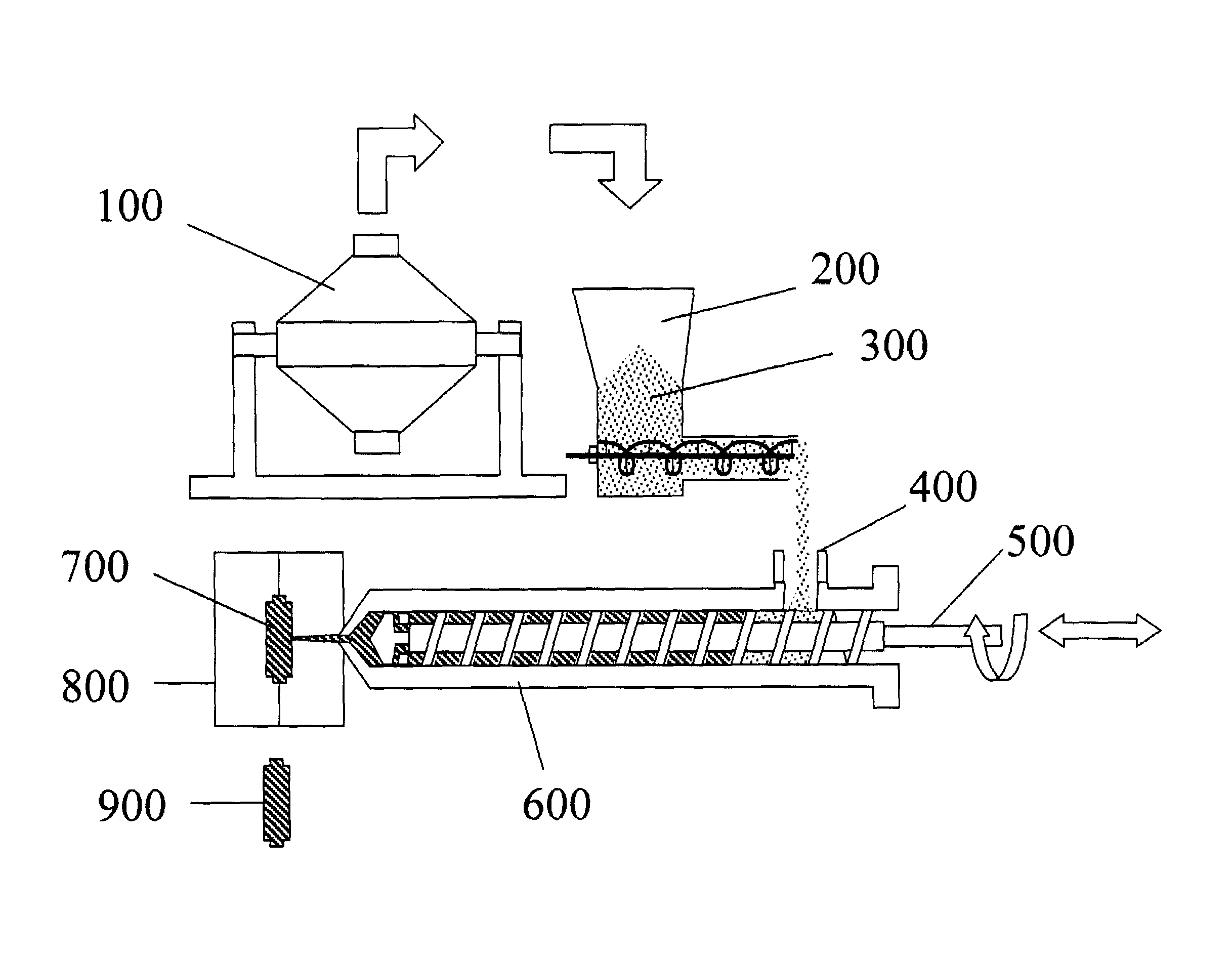
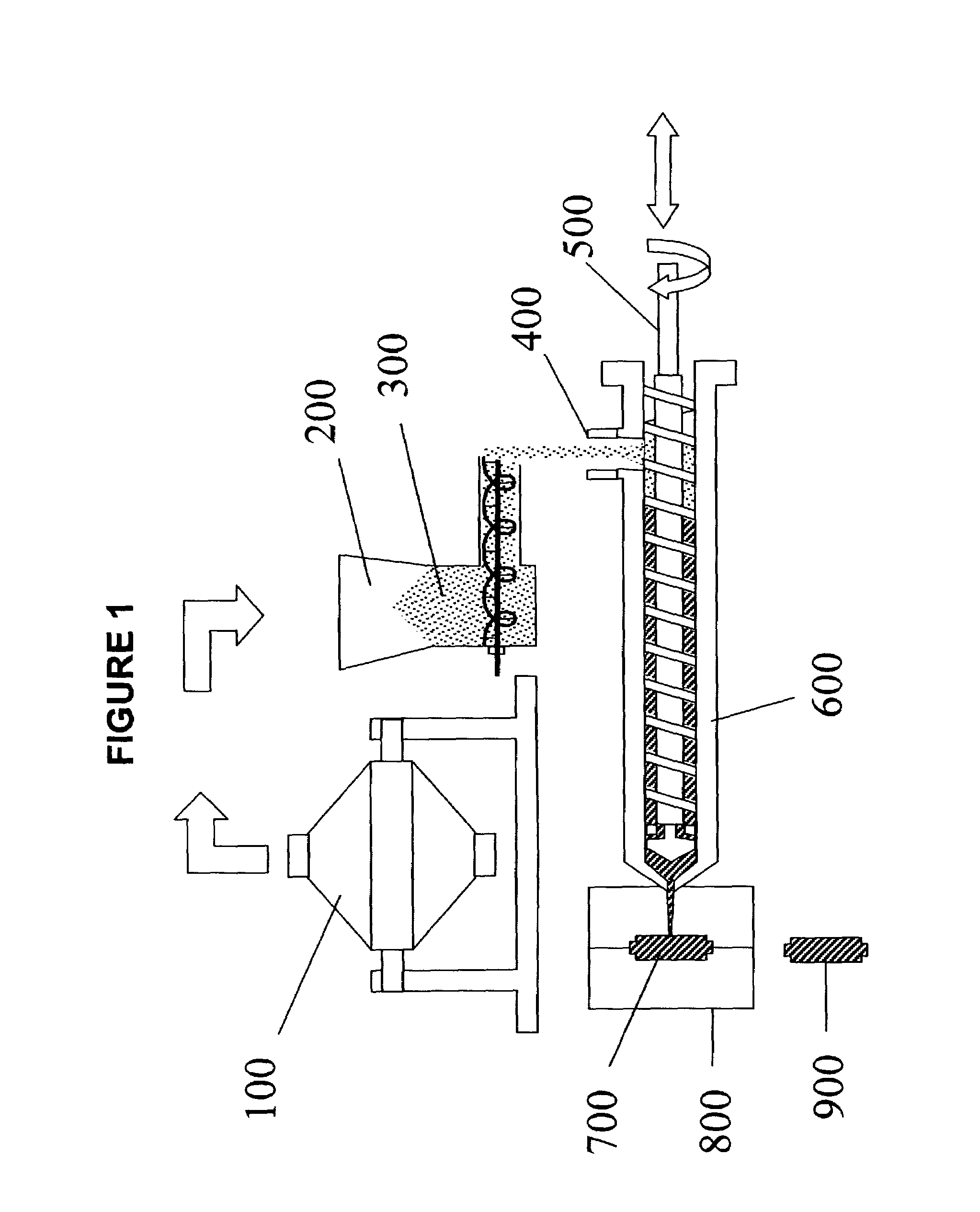
[0031]It is a particular advantage of the invention that the solvent content of the molding mixture can be adjusted easily to tune the viscosity and / or shrinkage of the molding mixture to optimize production of a given part. For example, the moisture content of a batch of molding mixture can be increased by simply adding a measured amount of water to a known weight of molding mixture and remixing for several minutes in a small twin cone blender or other suitable mixing device.

Problems solved by technology

Pre-compounding of metal and CERMET injection molding and extrusion materials adds significant cycle time, capital equipment requirements, and labor cost to the overall part manufacturing process.
Equipment used for either batch or continuous compounding of injection molding materials is intrinsically expensive for several reasons.
First, the high viscosities of typical molding materials mandate very rugged mixer design and construction, as exemplified by sigma blade mixers and twin screw extruders.
Secondly, heating means and temperature controllers are required.
Lastly, continuous compounding requires expensive precision feeders for metering powder and liquid ingredients.
Moreover, in batch and continuous compounding of aqueous binder compositions at elevated temperatures, rapid loss of water by evaporation leads to difficulty in the precise control of the moisture content of the finished product.
This is a serious difficulty since moisture content exerts profound influences on the flow properties of the material during injection molding, and on the total shrinkage of the part or shape during drying and sintering with direct impacts on mold filling, green part shape retention, and final product dimensions.
Finally, inevitable yield losses associated with the pre-compounding step add further to overall PIM, MIM, or CIM processing costs.

Method used


Image

  • Method of producing shared articles
  • Method of producing shared articles
  • Method of producing shared articles

Examples


example 1

[0055]A dry powder mixture was made by thoroughly mixing 2000 grams of Anval−22 micron 17-4 PH stainless steel powder (Powder Products Division of Carpenter Technologies, Reading, Pa.) with 44.44 grams of powdered agar (TIC PRETESTED® Agar Agar 100) in a Paul O. Abbe, 0.5 gallon (1.82 liter) capacity sigma-blade mixer running at about 20 rpm for 5 minutes at room temperature. A sigma-blade mixer was used because of its ready availability but less powerful and expensive mixing equipment would have served just as well. 177.6 grams of a saturated solution (approximately 0.25 wt. %) of calcium metaborate in distilled water was gradually added to the sigma mixer, and mixing was continued at 20 rpm for an additional 60 minutes at room temperature, producing a loose, damp powder mixture containing about 90 wt. % 17-4 PH stainless steel powder, 8.0 wt. % of the aqueous borate solution, and 2.0 wt. % agar. Based on visual observation of the material during mixing, the mixing was complete in ...

example 2

[0059]A dry powder mixture was made by thoroughly mixing 4000 grams of iron-2% nickel powder (Atmix P20F from Atmix Corporation, Hachinohe-shi, Aomori-ken, Japan) with 111 grams of powdered agar (TIC PRETESTED® Agar Agar 100) in a Paul O. Abbe, 0.5 gallon (1.82 liter) capacity sigma-blade mixer running at about 20 rpm for 5 minutes at room temperature.

[0060]A solution containing 1.8 grams of potassium nitrite (a rust inhibitor, Alpha Aesar CAS# 7758-09-0) and 3.5 grams of potassium tetraborate (Alpha Aesar CAS# 12045-78-2) in 400 cc of distilled water, were then added to the sigma mixer along with 0.8 gm of methyl p-hydroxy benzoate (biocide, Fisher Scientific CAS No. 99-76-3), and 0.6 gm of n propyl p hydroxybenzoate (biocide, Fisher Scientific CAS No. 94-13-3), and mixing was continued at 20 rpm for an additional 20 minutes, still at room temperature, producing a loose, damp powder mixture, similar to the product of example 1, containing about 89 wt. % Fe-2Ni metal powder, 9 wt. %...

example 3

[0063]Two batches of molding mixture, identical to that of Example 1 were prepared, except that the agar used for the second batch was TIC Agar Agar 150 FCC / NF (TIC 150). As in Example 1, the material was fed to the inlet hopper of a Boy 22 ton injection molding machine with all barrel and nozzle hearing zones set at 180° F. (82° C.) and screw rotation speed set at 45 rpm. A number of rectangular step thickness test bars were molded. The cavity dimensions for the step bar mold measured 1.5″ wide by 2.25″ long by 0. 125″ thick at on end, stepping down to 0.062″ thick at the other end. Feed screw back pressure was varied. Twenty-five bars were molded from the TIC 100 agar batch, and nineteen bars were molded from the TIC 150 material. The parts were dried in a drying oven set at 212° F. (100° C.) for 2 hours and cooled to room temperature and then each part was weighed. The average weight of the TIC 100 batch test bars was 25.224 grams with an estimated standard deviation of 0.145 gra...


PUM

PropertyMeasurementUnit
wt %aaaaaaaaaa
temperatureaaaaaaaaaa
molding pressureaaaaaaaaaa

Abstract

A novel process for manufacturing of injection molded metal, ceramic, and CERMET parts, in a manner amenable to high-volume, low-cost manufacturing, comprising the steps of forming a mechanical mixture of metal and / or ceramic powders at room temperature, a binder and a liquid carrier, said carrier being a solvent for the binder at elevated temperature; supplying the as-mixed components to the inlet hopper of an injection molding machine or extruder; molding or extruding green parts; and then drying and sintering the green parts to obtain net or near-net-shape finished metal, ceramic or CERMET parts.

Description

BACKGROUND OF THE INVENTION[0001]1. Field of the Invention[0002]The invention is simplified processes for shaping metal, ceramic, and CERMET (ceramic / metallic) parts and shapes from powder / binder mixtures. More particularly, the invention is directed to integration of the compounding and plasticizing processes for economical manufacturing of complex molded shapes which exhibit excellent green strength and which can be readily sintered to produce high quality net shape or near net shape parts.[0003]2. Description of the Related Art[0004]The production of sintered parts from injection molded “green” bodies is well known in the art. Generally, the green body is formed by injecting a fluid powder / binder mixture into a die cavity under pressure and allowing the injected material to cool and solidify in the cavity. The green body, now a self-supporting structure, is then removed from the die cavity and sintered. During the sintering process, the residual binder is volatilized and the powd...

Claims


Application Information

Patent Timeline
Patent Type & Authority Patents(United States)
IPC IPC(8): C04B33/32B22F9/00C04B35/00B22F3/22B28B1/24C04B35/632C04B35/634C04B35/636
CPCB22F3/22B28B1/24C04B35/632C04B35/634C04B35/63416C04B35/63444C04B35/636C04B35/6365B22F3/225B22F3/227B22F2998/00C04B2235/6022C04B2235/6021C04B2235/3409C04B2235/449
Inventor MORRIS, ROBERT CRAIG
Owner ROBERT CRAIG MORRIS
Learn More