Exothermic welding

a technology of exothermic welding and welding ring, which is applied in the direction of aluminum-thermic welding apparatus, manufacturing tools, other domestic objects, etc., can solve the problems of added expense involved in providing two grain sizes and packing, and the smokeless procedure which has been employed in the past has not attained the other desirable goals heretofore described, and achieves the effect of easy ignitable weld metal

Active Publication Date: 2006-02-07
HARGER
View PDF7 Cites 36 Cited by
  • Summary
  • Abstract
  • Description
  • Claims
  • Application Information

AI Technical Summary

Benefits of technology

[0007]It would also be desirable to eliminate the need for the tin plated steel disk which must first be inserted in the ignition cavity to retain the loose particulate weld material in the cavity prior to ignition. This would eliminate the need for the separate disk insertion step, the need to provide a disk at all, and would result in cleaner welds and cleaner molds after the welding procedure has been carried out.
[0008]It would also be desirable to eliminate the need for the plastic container from which the particulate weld metal is poured into the ignition cavity and the cumbersome step of having to pour the loose particulate weld material into the cavity and the need to dispose of the plastic container.
[0009]A smokeless exothermic welding procedure is currently available for exothermic welding in clean room environments. In such smokeless procedure a filter is employed with the mold to trap most of the emissions created in the exothermic welding process while al...

Problems solved by technology

Such exothermic welding eliminates the need for an outside source of heat or power and produces a permanent, corrosion resistant weld which cannot loosen and does not increase electrical resistance.
One reason is the added expense involved in providing two grain sizes and packing the two different grain sizes in the contain...

Method used


Image

  • Exothermic welding
  • Exothermic welding
  • Exothermic welding

Examples


Embodiment Construction

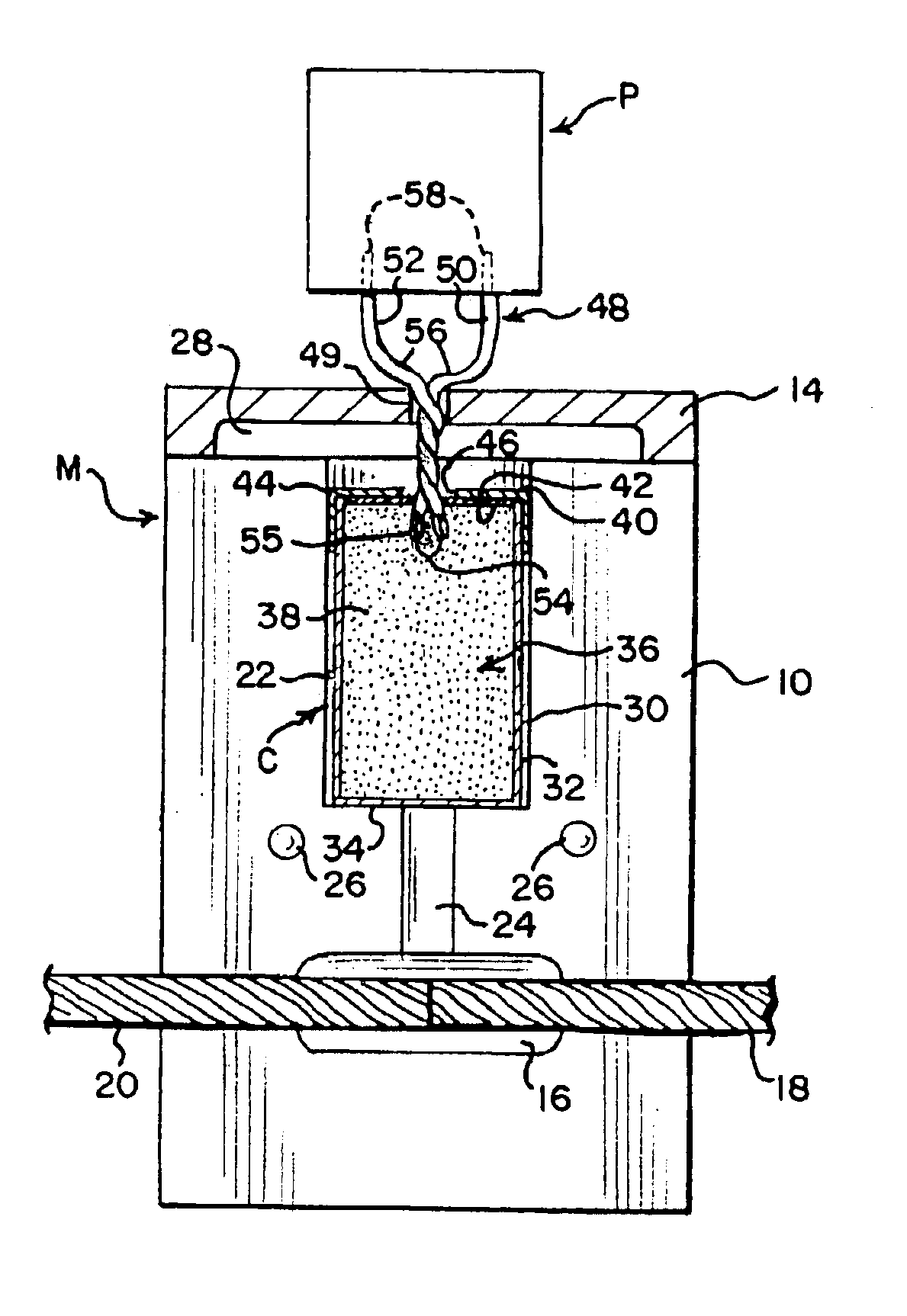
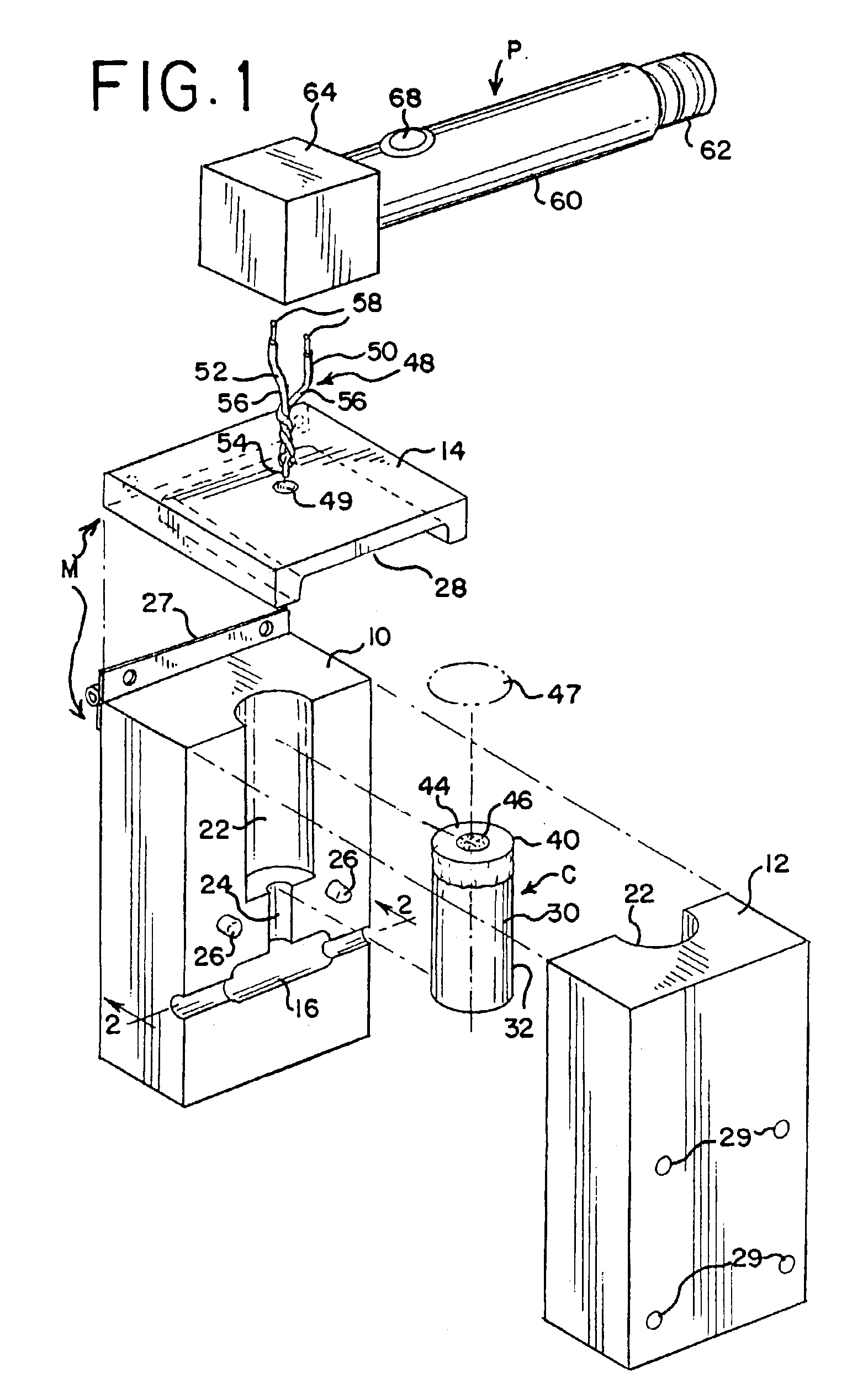
[0026]With particular reference to FIGS. 1 and 2, a preferred embodiment of exothermic welding assembly of the invention and for practicing the method of the invention comprises a mold M formed of a suitable material, such as graphite, for withstanding the extremely high temperatures of the exothermic welding process. The mold M as typically employed in exothermic welding is comprised of two mold halves 10 and 12 and a cover 14 as shown in FIG. 1. Mold half 10 includes one half of a weld cavity 16 which, for example as shown in FIG. 2, receives two members, such as cables 18 and 20, to position the cables in a closely adjacent relationship to each other to be exothermically welded together in the weld cavity 16. Although the members 18 and 20 as shown in the drawings as the members to be welded together are two cables, the members may be plates, pipes, rebar, etc., and the weld cavity 16 may open to a face of the mold M to accommodate such other shapes for example as shown in U.S. P...


PUM

PropertyMeasurementUnit
Temperatureaaaaaaaaaa
Lengthaaaaaaaaaa
Particle sizeaaaaaaaaaa

Abstract

An assembly and method are disclosed for exothermic welding including a mold which is formed of a material which withstands exothermic welding temperatures, and includes a weld cavity therein for positioning at least two members which are to be exothermically welded together adjacent to each other, and an ignition cavity communicating with the first cavity. The members which are to be exothermically welded together are positioned adjacent to each other using the weld cavity, and a weld metal cartridge is positioned in the ignition cavity. The cartridge comprises a container having copper walls which define a chamber therein, and a particulate weld metal in the chamber. The tip of an electrical igniter is positioned into the chamber of the container and particulate weld material therein, the igniter is electrically fired while the container is in the ignition cavity of the mold to melt the particulate weld material, and the contents of the ignition cavity are passed after melting the particulate weld metal to the weld cavity to weld the members together.

Description

BACKGROUND AND SUMMARY OF THE INVENTION[0001]The present invention relates to exothermic welding and improved assemblies and methods therefor.[0002]Exothermic welding has been employed in the past as an effective method of welding two or more members together which may be copper and / or steel, such as cables to cables, cables to ground rods, cables to steel surfaces including plates and pipes, cables to bus bars, cables to rebar and the like. Such exothermic welding eliminates the need for an outside source of heat or power and produces a permanent, corrosion resistant weld which cannot loosen and does not increase electrical resistance.[0003]To accomplish such welds the members to be welded together are positioned adjacent to each other utilizing a welding cavity in a mold formed of a material, such as graphite, which is capable of withstanding the extremely high temperatures of the exothermic welding process. Another ignition cavity in the mold contains a loose particulate weld met...

Claims


Application Information

Patent Timeline
IPC IPC(8): B23K31/02B23K23/00
CPCB23K23/00B23K2201/32B23K2201/06B23K2101/06B23K2101/32
Inventor HARGER, TIMOTHY R.HEYNIS, SPENCERHARGER, MARK S.
Owner HARGER
Why Eureka
Try Eureka