Electrical injection velocity-pressure switching and pressure holding device

a technology of electric injection and switching, which is applied in the direction of auxillary shaping apparatus, manufacturing tools, ceramic shaping apparatus, etc., can solve the problems of affecting the smoothness of the mold, the plastic will experience peaky and unsmooth surfaces, and the bleeding situation will occur, so as to facilitate the adjustment of v-p switching

Inactive Publication Date: 2006-02-07
IND TECH RES INST
View PDF6 Cites 12 Cited by
  • Summary
  • Abstract
  • Description
  • Claims
  • Application Information

AI Technical Summary

Benefits of technology

[0005]An object of the present invention is to provide a electrical injection V-P switching device and method thereof suitable for an electrically-operated injection molding machine for easily adjusting the V-P switching.

Problems solved by technology

If the position is switched too early a short fill situation will occur, and oppositely if the position is switched too late a bleeding situation will occur.
Similarly if the switching pressure is too high the plastic will have obvious parting lines, and oppositely if the switching pressure is unstable (the switching speed variation is too high) the plastic will experience peaky and unsmooth surfaces.
If the hold pressure is too high the plastic melt will adhere to the wall and cannot release properly whose residual will further cause flash or bleeding and if the hold pressure is severely high the mold will be forced open.
Oppositely if the hold pressure is too low the plastic will encounter warpage or have air holes which decreases the quality of the plastic.
From the above description, it is to be understood that the injection switching is of high importance and yet the precise adjustment cannot be easily achieved.
However this trial and error method is difficult to control stability and a high level of repetition during high volume manufacturing. FIG. 6 shows a conventional hydraulic injection unit 30 (powered by a hydraulic motor 32).
Due to lack of correction after each injection, the injection speed in the homestretch is deviated.
Furthermore after repeated usage of the injection unit 30, the process parameter of the injection unit 30 will be altered (such as fluid quality, operating temperature, and the like) and consequently affects the accuracy and repetition of the control and decreases the quality of the molded die.
Although the electrically-operated injection molding machines can eliminate the shortcomings of the hydraulic molding machines, they still possess problems such as manufacturing quantity because the device 50 can only perform closed-loop pressure control but cannot govern the injection speed and the injection shaft position.
This method cannot effectively perform a smooth switching from the injection phase to the pressure holding phase because the selection of the switching position cannot be optimized and stabilized.
Furthermore besides the pressure related characteristic parameter cannot be easily adjusted, the delay in the executing the switching order is significant because the switchable looping switches 52 of the conventional device 50 is designed to be external of the hardware.

Method used


Image

  • Electrical injection velocity-pressure switching and pressure holding device
  • Electrical injection velocity-pressure switching and pressure holding device
  • Electrical injection velocity-pressure switching and pressure holding device

Examples


Embodiment Construction

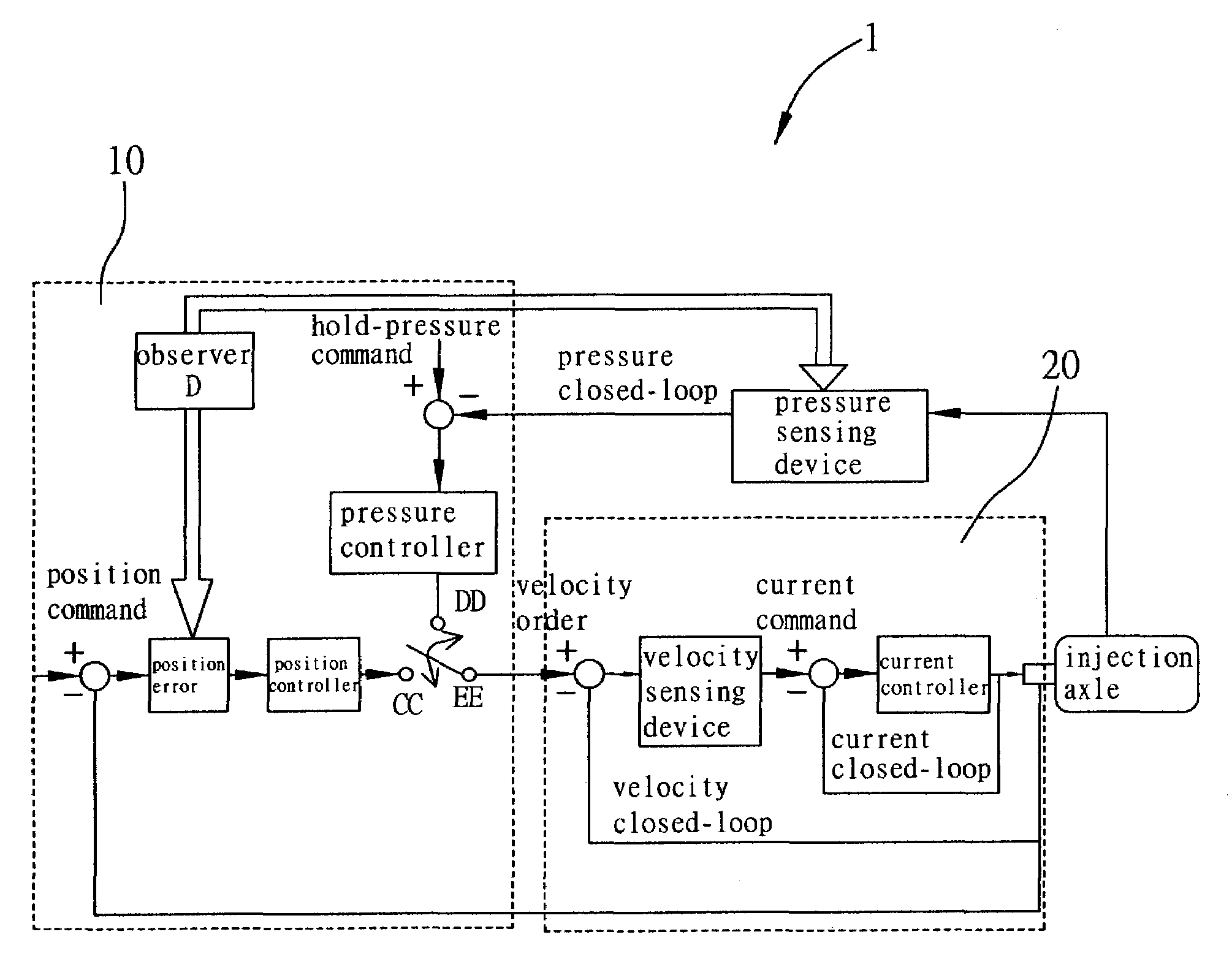
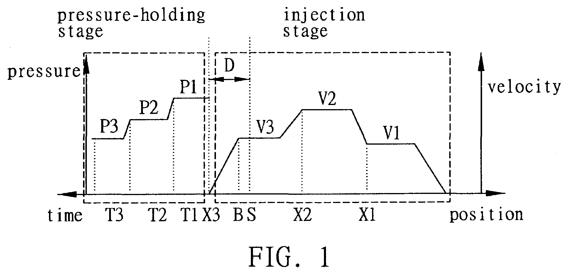
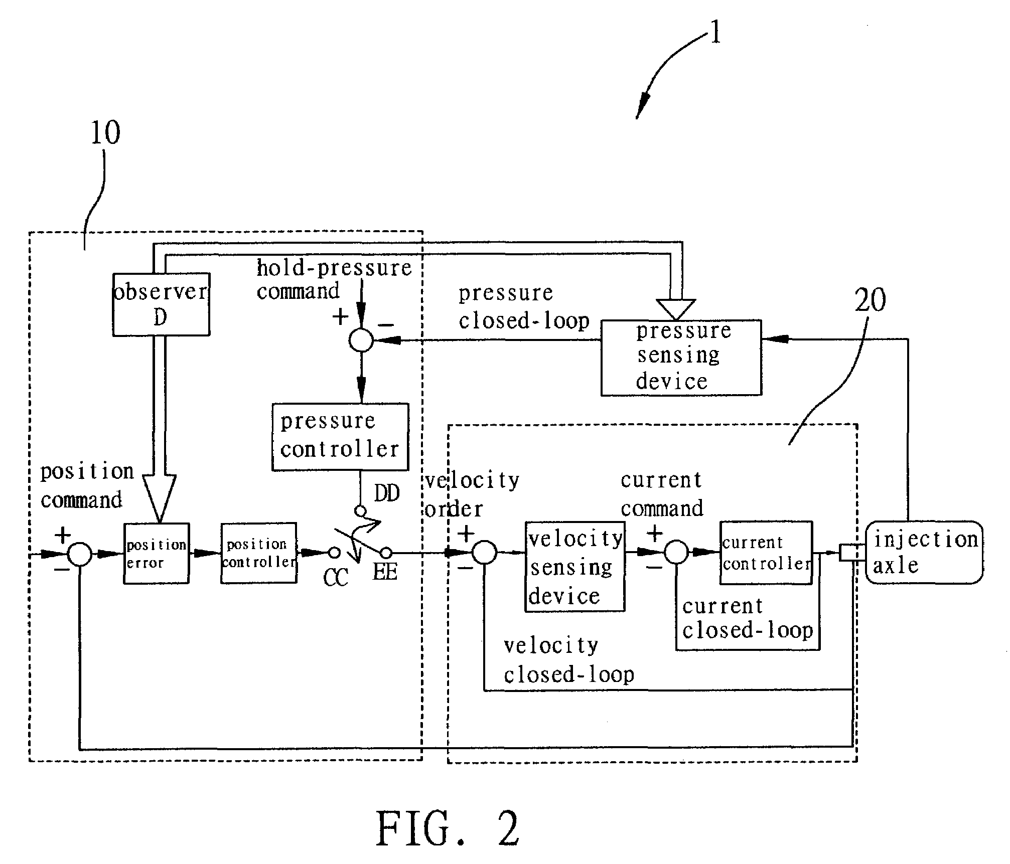
[0022]FIG. 7 shows the injection molding machine 40 of the present invention. The drive source comes from a servo motor 42 which is driven by a belt 44 or screw-type axle 45 driven by a gear mechanism to hold pressure on the mold 46 for solidification after the plastic is injected in it. The V-P switching and hold pressure control during the injection stage is the most important in determining the quality of the plastic piece. The V-P switching and hold pressure control device I of the present invention is used on the servo controller of these injection molding machines to precisely determine the switching position, pressure, velocity and the like parameters. In order to fully describe the preferred embodiment, please refer to the setup of the parameters in FIG. 1 as an example. The injection parameters are separated into different stages with three stages of injection control and three stages of pressure hold control. The stages and their corresponding values are limited to what is...


PUM

PropertyMeasurementUnit
velocity-pressureaaaaaaaaaa
pressureaaaaaaaaaa
velocityaaaaaaaaaa

Abstract

A velocity-pressure switching and pressure holding device and system for electrically-operated injection molding machines. The switching between closed-loop position control and closed-loop pressure control of a servo motor of an injection molding machine is quickly and smoothly achieved by a switchable loop switch to ensure the optimal control of the velocity-pressure switching during injection filling and pressure holding. Furthermore an adjustable observation value and a speed reducing set up for the injection axle before switching are provided to allow users to perform minor adjustments on the velocity-pressure switching during the slow down of the injection axle. The present invention easily and precisely achieves the optimal velocity-pressure switching parameters to facilitate better pressure holding ability to increase the quality of the plastic products.

Description

FIELD OF THE INVENTION[0001]The present invention generally relates to an electrical injection velocity-pressure switching and pressure holding device and method thereof; and particularly, related to an electrical injection velocity-pressure switching and pressure holding device and method thereof which easily and precisely achieves the optimal V-P switching.BACKGROUND OF THE RELATED ART[0002]High-volume injection molding machines can be either categorized by the type of injection unit or clamping unit regardless of the molding material. There are two main categories of injection units are the ram type and the screw type and two main categories of clamping units are the hydraulic type and the mechanical type. The source of the driving unit can be either hydraulic or electrical. The stringent control of the hold pressure of the injection process is the key element to controlling the final quality of the plastic molds. Common problems such as surface wrinkles, warpage, distortion, fla...

Claims


Application Information

Patent Timeline
Patent Type & Authority Patents(United States)
IPC IPC(8): B29C45/77
CPCB29C45/77B29C2045/1792B29C2045/776B29C2945/76006B29C2945/76498B29C2945/76936B29C2945/76568B29C2945/76595B29C2945/76665B29C2945/76675B29C2945/76525
Inventor LIU, HSING CHANGCHIEN, YU-WEI
Owner IND TECH RES INST
Why Eureka
Try Eureka