Bioabsorbable marker having external anchoring means

a bioabsorbable marker and anchoring technology, applied in the field of tissue markers, can solve the problems of destroying the function of metal markers to accurately mark the biopsy site, and prone to migrate within the tissu

Active Publication Date: 2006-02-07
MEDICAL DEVICE TECH
View PDF7 Cites 138 Cited by
  • Summary
  • Abstract
  • Description
  • Claims
  • Application Information

AI Technical Summary

Benefits of technology

[0041]Advancing the plunger in a trailing-to-leading the direction causes the marker to drive the clip in the same direction and causes the opposed jaws to be driven toward one another because the pins are constrained against radial travel by the cylindrical sleeve and because the pins cannot be displaced in a radially outward direction when they are compelled to slide out of the leading recesses onto the respective raised surfaces formed in the main body. The respective distal free ends of the jaws firmly grasp tissue therebetween, permanently anchoring the clip to the tissue.
[0042]Continued advancement of the plunger enables the pins to slide from the respective raised surfaces into engagement with the trailing recessed surfaces, thereby releasing pressure form the pins and enabling withdrawal of the delivery catheter and cylindrical sleeve.
[0043]Without limitation to the structure of the sixth embodiment, the sixth novel method includes the steps of forming a blind cylindrical bore in a leading end of a cylindrical marker, providing a clip having a base received within the blind cylindrical bore, providing the clip with a pair of opposed jaws that are disposed in substantially parallel relation to one another when in repose, forming a first pair of recesses in a main body of the clip in diametrically opposed relation to one another, forming a second pair of recesses in the trailing end of the main body of the clip in diametrically opposed relation to one another, thereby forming a pair of diametrically opposed raised areas in said main body between the leading and trailing recesses, forming a pair of diametrically opposed, radially inwardly extending pins in a cylindrical sleeve that ensleeves a delivery catheter that ensleeves said clip, forming a first opening in said delivery catheter to accommodate a first pin and forming a second opening formed in the delivery catheter in diametric opposition to the first opening to accommodate a second pin, positioning a leading end of the delivery catheter and a leading end of the cylindrical sleeve in substantial alignment with one another so that advancing a plunger introduced into a trailing end of a lumen of said delivery catheter in a trailing-to-leading direction causes the marker to drive the clip in the same direction and causes the opposed jaws to be driven toward one another because the pins are constrained against radial travel by the cylindrical sleeve and because the pins cannot be displaced in a radially outward direction when they are compelled to slide out of the leading recesses onto the raised surfaces formed in said main body. The respective distal free ends of the jaws firmly grasp tissue therebetween, permanently anchoring the clip to the tissue. Continued advancement of the plunger displaces the clip until the pins in the cylindrical sleeve enter into registration with the recesses formed in the trailing end of the main body of the clip, thereby releasing pressure from the pins and enabling leading-to-trailing retraction of the delivery catheter and cylindrical sleeve.

Problems solved by technology

However, metallic markers are prone to migrate within the tissue.
Thus, when they are found after the passage of an extent of time, they may have migrated from their initial position in or near the lesion or tumor, thereby destroying their functionality as a marker to accurately mark the biopsy site.

Method used


Image

  • Bioabsorbable marker having external anchoring means
  • Bioabsorbable marker having external anchoring means
  • Bioabsorbable marker having external anchoring means

Examples


second embodiment

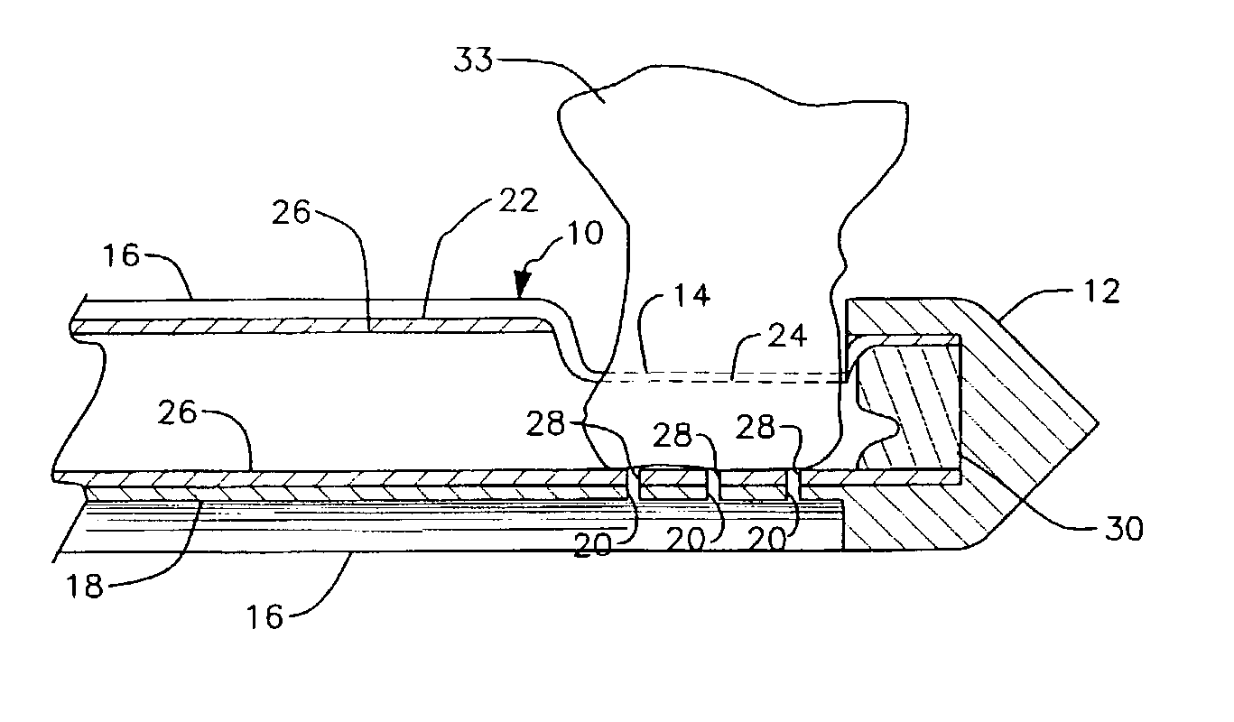
[0130]A second embodiment is depicted in FIGS. 8–14. Core biopsy needle 10 and delivery catheter 22 are also used in this embodiment, but said parts are not depicted to simplify the drawings.

[0131]Metallic straight member 36 of the first embodiment is replaced in this second embodiment by clip 40 that is permanently bonded by suitable means to bioabsorbable marker 34. Specifically, clip 40 has an annular base 42 that is received within an annular cavity 44 formed in leading end 34b of marker 34. A central bore 46 is formed in marker 34 in coincidence with its longitudinal axis of symmetry and a similar bore 48 is formed in annular base 42 of clip 40 so that bores 46 and 48 are in axial alignment with one another when the trailing end of clip 40 is secured to the leading end 34b of marker 34.

[0132]Clip 40 is preferably of metallic construction but may also be made of other materials as mentioned above.

[0133]The FIG. 8 configuration of clip 40 is its in repose, normally closed configu...

third embodiment

[0139]A third embodiment is depicted in FIGS. 15–22. This embodiment is the only embodiment where the marker and the metal hook are manufactured separately and do not combine with one another until a site is marked. This embodiment is also the only embodiment having two plungers, hereinafter referred to as the inner and outer plungers.

[0140]As depicted in FIG. 15, inner plunger 60 has a trailing section 62 of a first diameter, a leading section 66 of the same diameter as said trailing section, a middle section 64 having an enlarged diameter relative to trailing section 62 and leading section 66, and a tapered leading section 67 that terminates in sharp point 68. Annular step 63 is formed where section 62 meets section 64, and annular step 65 is formed at the juncture of sections 64 and 66.

[0141]Outer plunger 60a is of cylindrical configuration and has a central bore 61 that accommodates trailing section 62 of inner plunger 60. Accordingly, inner plunger 62 is concentrically disposed...

fourth embodiment

[0156]A fourth embodiment is depicted in FIG. 23. Beveled annular surface 34c is formed in leading end 34b of marker 34 and is in open communication with blind bore 70. Jaws 50, 52 of clip 40 have beveled trailing surfaces 40a, 40a and beveled leading surfaces 40b, 40b formed therein. In this way, when outer plunger 60a is advanced in a trailing-to-leading direction, denoted by directional arrow 59, beveled annular surface 34c bears against beveled surfaces 40a, 40a, causing jaws 50, 52 of clip 40 to converge toward one another and to pinch tissue 33, not shown, therebetween.

[0157]In all other aspects, the fourth embodiment of the invention works in the same way as the structure of the third embodiment.

[0158]A fifth embodiment is depicted in FIGS. 24–29. Bioabsorbable marker 34 has an elongate cylindrical structure in this embodiment. Cross-shaped bore 74a is formed in marker 34 by an elongate slot 78 that intersects with a truncate slot 80, just as in the third embodiment in connec...


PUM


Abstract

A clip and a bioabsorbable marker are employed to mark a biopsy site. The former provides a permanent marker that is clamped onto tissue and that cannot migrate from the site over time. The latter is gradually bioabsorbed over time but the time may vary widely from weeks to months. In most embodiments, the clip and marker are integrally formed with one another at the time of manufacture. In one embodiment, the clip and marker are independently made but are joined to one another during the site-marking process. The markers are deployed by core biopsy needles of the type employing a vacuum, of the type that does not employ a vacuum, and by coaxial biopsy needles.

Description

BACKGROUND OF INVENTION[0001]1. Field of the Invention[0002]This invention relates, generally, to tissue markers. More particularly, it relates to a bioabsorbable marker having an anchoring means that is not bioabsorbable and that is external to the bioabsorbable part of the marker.[0003]2. Description of the Prior Art[0004]Placing a marker in or near a lesion or tumor upon which a biopsy procedure has been performed enables a physician to find the lesion or tumor at a date weeks or months after the biopsy, depending upon the rate of degradation of the marker. The marker may be observed under ultrasound, it may be radiopaque, or the like.[0005]In some cases, the marker material may be completely bioabsorbed by the time the physician needs to locate the lesion or tumor again. One of the ways to enable such re-finding of the lesion or tumor is to attach a metallic marker to the bioabsorbable marker so that the metallic marker may be found by X-ray or other techniques long after the ma...

Claims


Application Information

Patent Timeline
Patent Type & Authority Patents(United States)
IPC IPC(8): A61B19/00A61BA61B1/00A61B5/05A61B10/00A61B17/00
CPCA61B19/54A61B2019/5487A61B2019/5408A61B2017/00004A61B90/39A61B2090/3908A61B2090/3987
Inventor FISHER, JOHN S.AHARI, FREDERICK
Owner MEDICAL DEVICE TECH
Why Eureka
Try Eureka