Optoelectronic sensor device

a sensor device and optoelectronic technology, applied in the direction of vehicle cleaning, instruments, specific gravity measurement, etc., can solve the problems of undesirable blocking of ambient light into the optoelectronic sensor device, requiring the use of relatively elaborate and costly special components, and requiring the use of special components. , to achieve the effect of simple and effective heating device, good printability and cost-effective production

Inactive Publication Date: 2006-02-07
LEOPOLD KOSTAL GMBH & CO KG
View PDF16 Cites 49 Cited by
  • Summary
  • Abstract
  • Description
  • Claims
  • Application Information

AI Technical Summary

Benefits of technology

[0009]The optoelectronic sensor device in accordance with the present invention has the advantage that the heating device arrangement is relatively more cost-effective to produce and results in free space located in the immediate vicinity of the pane (i.e., the windshield) which can be used for accommodating additional components such as light sensors.
[0010]This is possible as the heating device is arranged on an additional circuit substrate that is arranged parallel to the surface of the pane and that is electrically connected with a main printed circuit board. An especially simple and effective heating device is formed by a resistance element placed on the circuit substrate, especially on the side of the circuit substrate facing away from the pane.
[0011]A plate-shaped ceramic substrate may be used as the circuit substrate because of its thermal stability and good printability, especially in the standard silk-screen printing process. A conventional rigid or flexible circuit board may also be used as the circuit substrate.

Problems solved by technology

The heating device arrangement disclosed in U.S. Pat. No. 5,543,923 requires the use of relatively elaborate and costly special components.
Further, this heating device arrangement results in blocking the penetration of ambient light into the inside of the sensor device over a relatively large area.
The blocking of ambient light into optoelectronic sensor devices is undesirable at times. As such, in the case of a heating device arrangement blocking ambient light, the sensor device requires an ambient light receiving area that is located outside of the area shaded by the heating device.
However, adding such an ambient light receiving area enlarges the total dimensions of the sensor device which is generally considered as being disadvantageous.

Method used


Image

  • Optoelectronic sensor device
  • Optoelectronic sensor device
  • Optoelectronic sensor device

Examples


Embodiment Construction

)

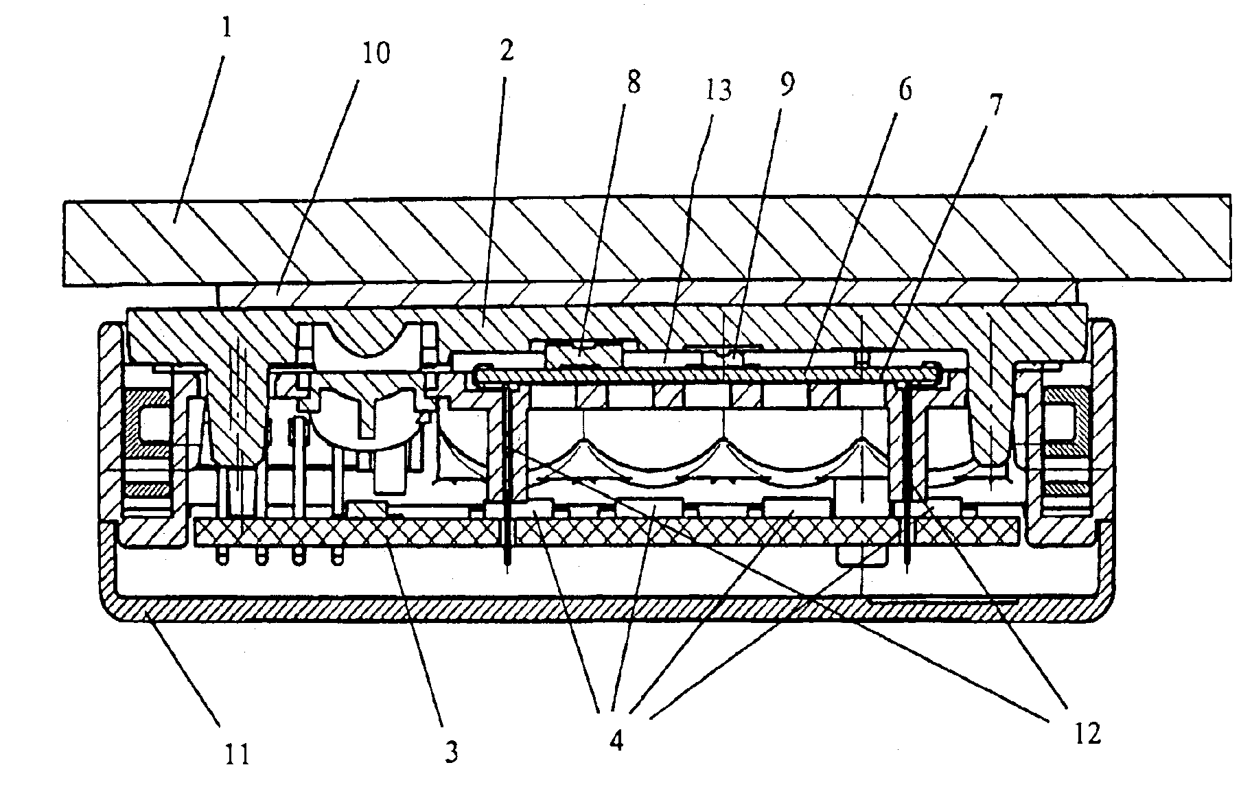
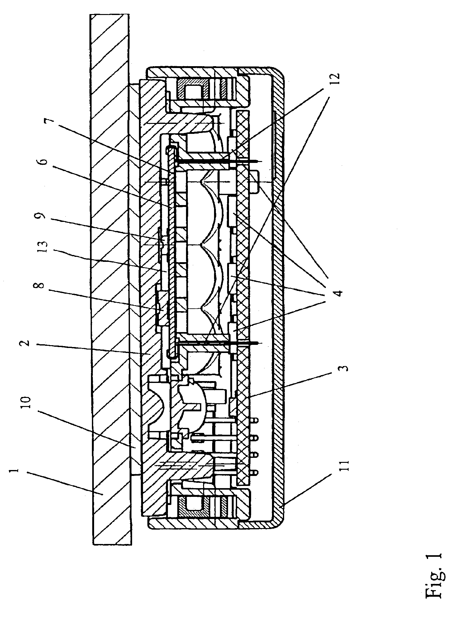
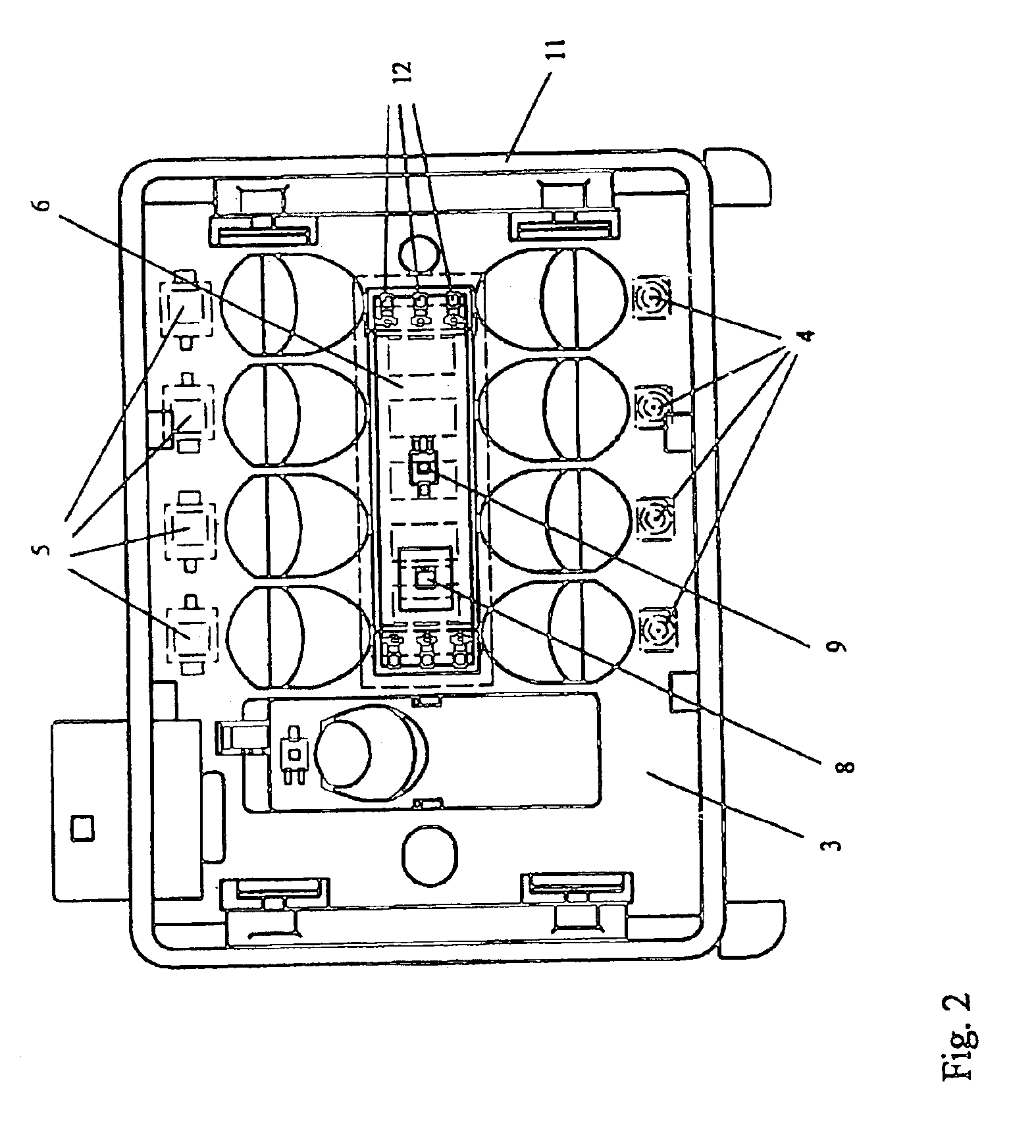
[0015]Referring now to FIGS. 1 and 2, an optoelectronic sensor device for detecting the degree of wetting of a precipitation-covered transparent pane 1 in accordance with the present invention is shown. The optoelectronic sensor device generally includes a beam guide body 2, beam transmitters 4, and beam receivers 5. Beam guide body 2 guides light beams from beam transmitters 4 towards pane 1 and guides light beams reflected from the pane towards beam receivers 5.

[0016]To this end, beam guide body 2 includes pairs of optical lenses which are associated with respective pairs of beam transmitters and receivers 4, 5. A first lense of each pair of lenses parallelize divergent bundle beams transmitted from an associated beam transmitter 4 towards the outer surface of pane 1 for eventual receipt by the associated beam receiver 5. A second lense of each pair of lenses focus the parallel bundle of light beams reflected off of the outer surface of pane 1 onto the associated beam receiver 5....


PUM


Abstract

An optoelectronic sensor device for detecting precipitation on an outer surface of a transparent pane. The sensor device includes a beam guide attached to an inner surface of the pane and a circuit board offset from the inner pane surface. A beam transmitter is arranged on the circuit board to transmit, along a transmission beam path, a light beam toward the pane via the beam guide. A beam receiver is arranged on the circuit board to receive, along a reception beam path, a light beam reflected from the outer surface of the pane via the beam guide. A circuit substrate, electrically connected to the circuit board, is arranged parallel to the pane between the pane and the circuit board. An installation space separates the circuit substrate from the inner pane surface. A heating device is arranged on the circuit substrate in an area lying outside of the beam paths.

Description

CROSS-REFERENCE TO RELATED APPLICATIONS[0001]This is a continuation of International Application PCT / EP03 / 05667, published in German, with an international filing date of May 30, 2003, which claims priority to DE 102 24 692.0 filed Jun. 4, 2002, which are both hereby incorporated by reference.BACKGROUND OF THE INVENTION[0002]1. Field of the Invention[0003]The present invention generally relates to an optoelectronic sensor device for detecting the degree of precipitation wetting of a transparent pane in which the optoelectronic sensor device has a beam guide body associated with beam transmitters and receivers arranged on a main board and a heating device located in an area lying outside of the beam paths of the beam transmitters and receivers.[0004]2. Background Art[0005]Optoelectronic sensor devices are typically employed to influence a windshield washer system as a function of the amount of precipitation located on the windshield of a motor vehicle. Such devices generally employ a...

Claims


Application Information

Patent Timeline
Patent Type & Authority Patents(United States)
IPC IPC(8): G02B6/42B60S1/08
CPCB60S1/0822B60S1/0837B60S1/0888B60S1/0881
Inventor HAGEN, FRANKWEBER, THOMASLEVERS, JURGEN
Owner LEOPOLD KOSTAL GMBH & CO KG
Why Eureka
Try Eureka