Permanent magnet field small DC motor

a permanent magnet field and dc motor technology, applied in the direction of dynamo-electric machines, electrical apparatus, magnetic circuit shapes/forms/construction, etc., can solve the problems of increased cogging torque, increased cogging torque, and difficulty in conducting a compression molding of rare-earth-based melt-spun flakes together with a resin-binder, so as to enhance the high-precision revolving performance and reduce cogging torque , the effect of strong

Inactive Publication Date: 2006-02-07
PANASONIC CORP
View PDF42 Cites 25 Cited by
  • Summary
  • Abstract
  • Description
  • Claims
  • Application Information

AI Technical Summary

Benefits of technology

[0016]A permanent magnet field small DC motor of the present invention has a stronger static magnet field in the air-gap between an armature and the magnet, by employing an arc-shaped rare earth magnet of 1 mm thick or less fabricated by compression molding. New control means for controlling distribution of flux density in the air-gap between an armature and the magnet as proposed by the present invention enhances the high precision revolving performance by further reducing cogging torque in compact and high output motors.

Problems solved by technology

However, it is also mentioned that there is a difficulty in conducting a compression molding of rare-earth-based melt-spun flakes together with a resin-binder.
One of the problems with the permanent magnet field small DC motor comprising the arc-shaped rare earth magnet fabricated through the above extrusion molding, which provides a stronger static magnet field in an air-gap to the armature 3 as compared to a ferrite magnet motor, is an increased cogging torque.
The cogging torque is a substantial problem among the permanent magnet field small DC motors which are expected to be compact in size, yet required a high mechanical output with an accurate revolving performance.
This can lead to a crack, tip-cut, etc. of the magnet 1 at the engagement portion, or the magnet 1 even might drop off the frame.
Thus, there is a possibility of serious hazards in the reliability of the permanent magnet field small DC motors in the above disclosure.
However, there is a difficulty in fabricating by, for example, extrusion molding an arc-shaped rare earth magnet of maximum thickness 1 mm or less that has two or more shapes in the cross section along the thrust direction.
Cutting a thin arc-shaped rare earth magnet 1 at a high precision level is quite difficult work, and cracks and drop-offs readily arise to invite a poor manufacturing yield rate.
Furthermore, particles of the raw material of rare earth magnet may increase the difficulty in finishing an arc-shaped the rare earth magnet 1 to be ready for mounting in a soft-magnetic frame 2.
H6-236807, meaning that “since there is a substantially wide variation in the weighing at molding, it has been considered to be difficult to provide by compression molding thin arc-shaped magnets having a maximum thickness of 1 mm or less at a dimensional accuracy ±30 μm”.
Even if the problem is solved, however, the mechanical strength of the compression molded rare earth magnet is low at the room temperature area, and brittle, because of a lower amount of resin contained therein.
So, the arc-shaped rare earth magnets fabricated by compression molding are not suitable for fixing and securing in a soft-magnetic frame in accordance with the method taught in the Japanese Patent Laid-open Publication No.

Method used


Image

  • Permanent magnet field small DC motor
  • Permanent magnet field small DC motor
  • Permanent magnet field small DC motor

Examples


Embodiment Construction

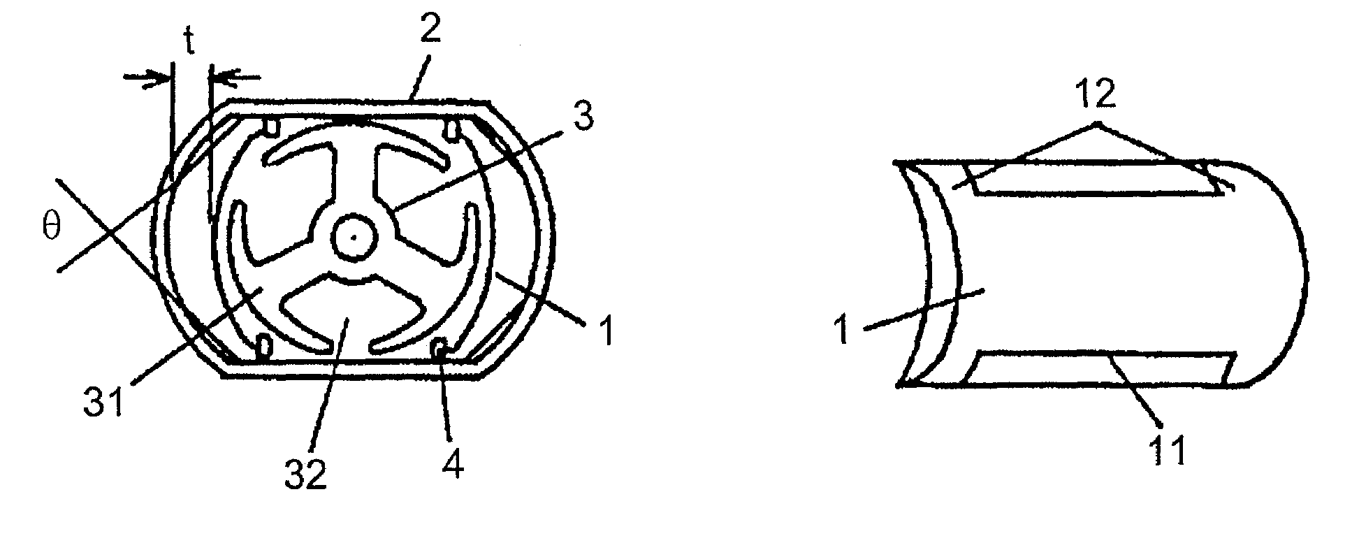
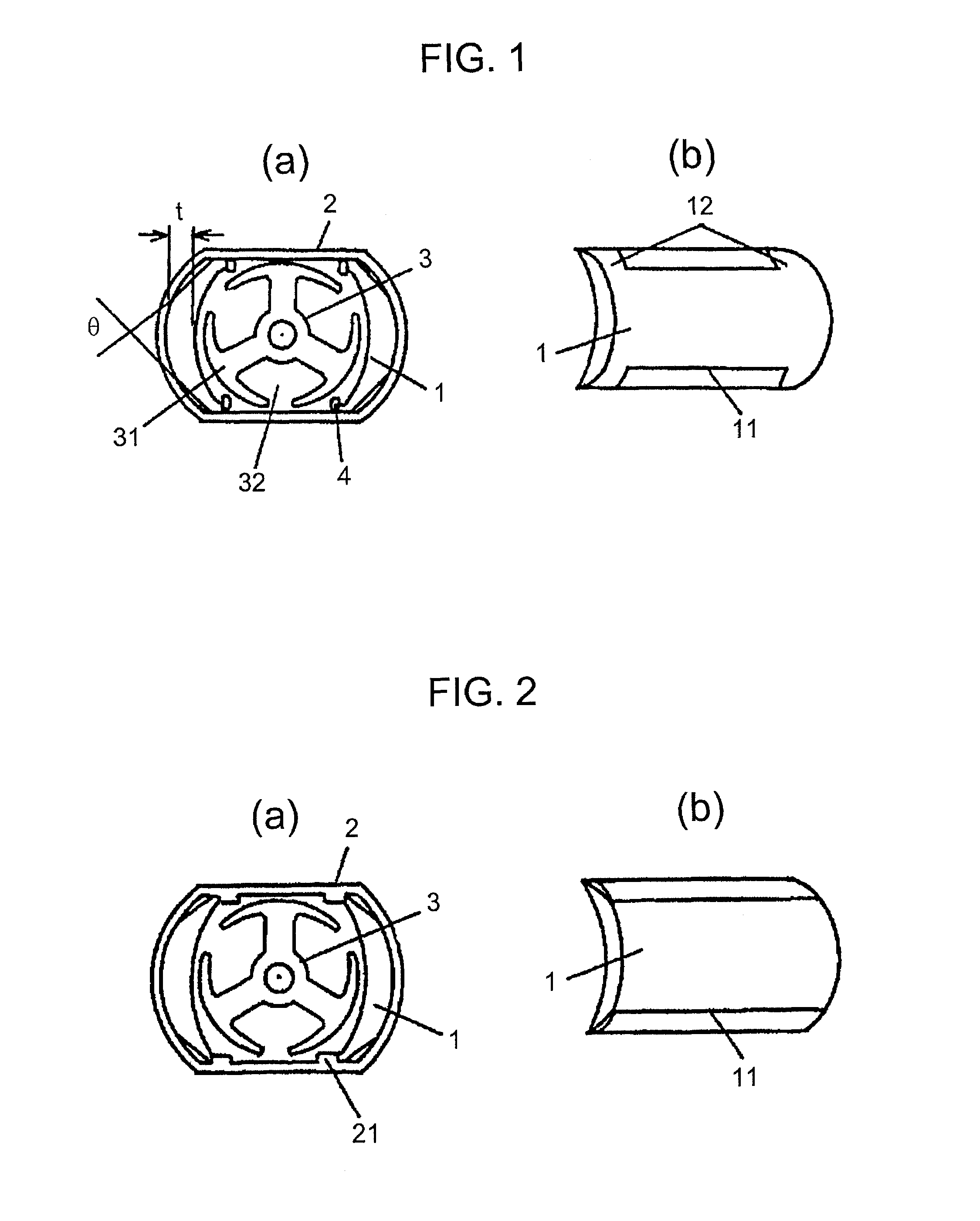
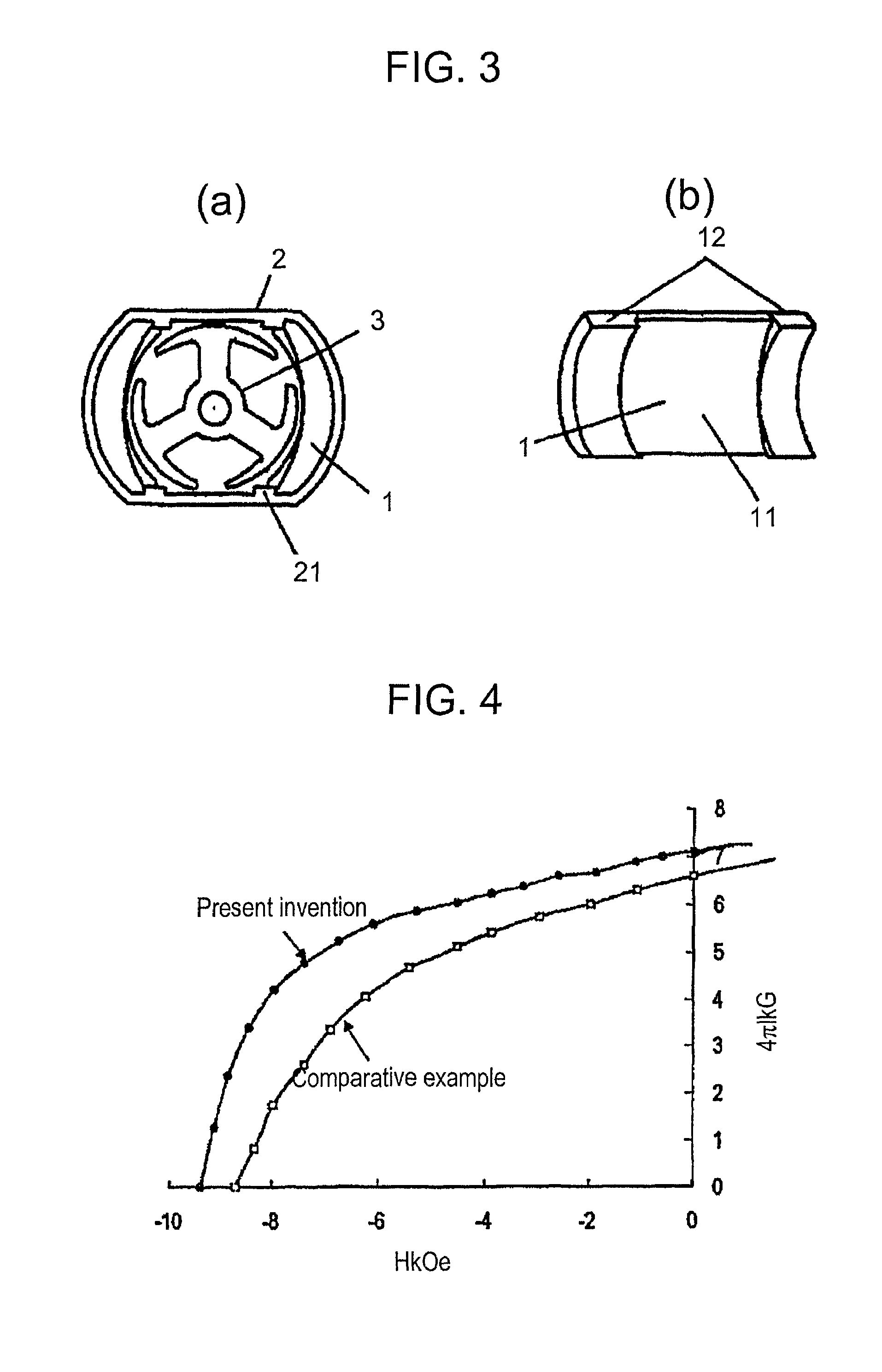
[0024]Referring to FIGS. 1(a) and 1(b), an arc-shaped rare earth magnet 1 having a maximum thickness t of 1 mm or less is fabricated by compression molding from rare earth-iron based melt-spun flakes mixed with a binder, the outer surface 12 at both ends in the thrust direction of the magnet are shaped in accordance with the inner surface of a soft-magnetic frame 2, while a certain clearance is provided between the outer surface of the magnet 1 in the middle part in the thrust direction at both ends 11 in the circumferential direction and the soft-magnetic frame 2. The magnets are fixed and secured opposing to each other with an armature 3 disposed in between, to complete a finished permanent magnet field small DC motor.

[0025]An objective of forming the clearance is to provide the arc-shaped rare earth magnet 1 with a certain specific portion having no back yoke, in the middle part, in the thrust direction at both ends 11 in the circumferential direction. Thereby, the specific porti...


PUM

PropertyMeasurementUnit
thicknessaaaaaaaaaa
thicknessaaaaaaaaaa
thicknessaaaaaaaaaa

Abstract

A permanent magnet field small DC motor includes an arc-shaped rare earth magnet of maximum thickness 1 mm or less fabricated by compression molding from rare earth iron based melt-spun flakes and a binder. The magnet is provided with a certain specific portion at both ends in the circumferential direction, which has no back yoke when the magnet is press-fit in a soft-magnetic frame. The arc-shaped rare earth magnet fabricated by compression molding from a material containing more rare earth iron based melt-spun flakes exhibits simultaneous increase of both a remanence as a function of magnetizing field and a coercivity; and hence, exhibits a well-balanced demagnetization curve even in an unsaturated magnetized state.

Description

TECHNICAL FIELD[0001]The present invention relates to a permanent magnet field small DC motor having a thin arc-shaped rare-earth magnet of a maximum thickness of 1 mm or less. The motor operating on a low starting voltage and a low starting current yet yielding a high output with an accurate revolving performance at a lower cogging torque. A typical field of application of these motors is in an optical pickup for a MD, CD-ROM and the like audio-visual equipment.BACKGROUND ART[0002]FIG. 1(a) is a cross sectional view at a key portion of a permanent magnet field small DC motor relating to the present invention; FIG. 1(b) shows an arc-shaped magnet used in the motor. In the drawings, a pair of arc-shaped magnets 1, a soft-magnetic frame 2, an armature 3, which includes a brush-rectifier, a rotating shaft and a bearing, and a U-shaped spring 4 for pressing and securing the pair of arc-shaped magnets 1 in the soft-magnetic frame 2 are shown. The permanent magnet field small DC motor und...

Claims


Application Information

Patent Timeline
Patent Type & Authority Patents(United States)
IPC IPC(8): H02K21/26H02K23/04H02K1/17H02K15/03
CPCH02K23/04H02K1/17
Inventor YAMASHITA, FUMITOSHISASAKI, YUICHIRO
Owner PANASONIC CORP
Why Eureka
Try Eureka