Vehicle positioning apparatus

a positioning apparatus and vehicle technology, applied in the direction of vehicle position/course/altitude control, process and machine control, instruments, etc., can solve the problems of increasing the effect of many of these factors, affecting the safety of the vessel, so as to achieve the effect of simple operation

Inactive Publication Date: 2006-02-07
WORTSMITH JOE W
View PDF18 Cites 38 Cited by
  • Summary
  • Abstract
  • Description
  • Claims
  • Application Information

AI Technical Summary

Benefits of technology

[0021]It is a further object of the present invention to provide for a vehicle positioning system that is inexpensive.
[0022]It is a further object of the present invention to provide for a vehicle positioning system that is simple to operate.

Problems solved by technology

Larger vessels have considerable inertia, and thus compensation for all of these effects becomes progressively more difficult as the size of the ship increases.
Also, the effect of many of these factors is increased due to the low water speed at which docking generally takes place.
Failure to properly compensate for these multiple and changeable effects may result in a disastrous collision between the vessel and its dock.
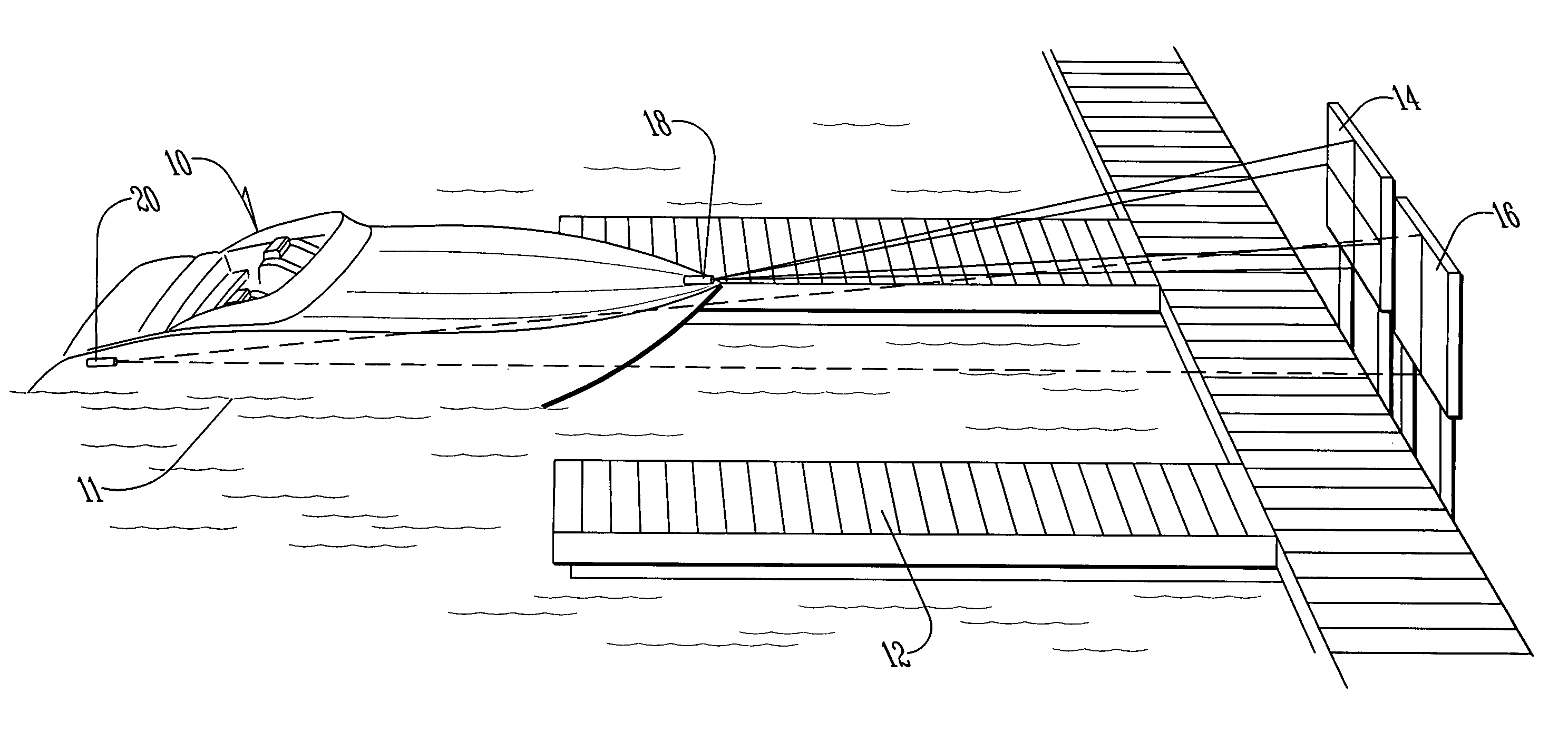
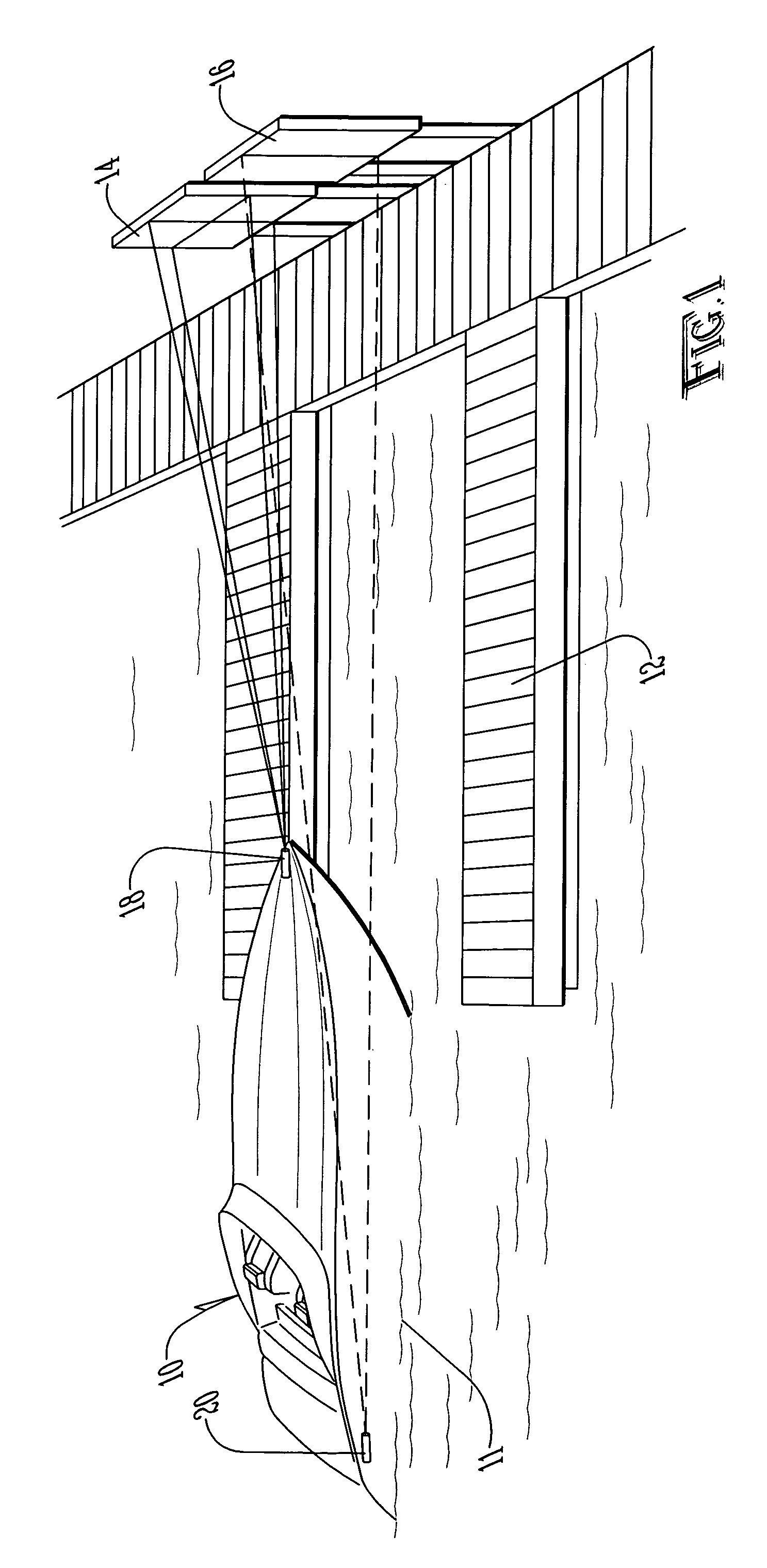
In particular, it may be recognized that even if the bow of the vessel is correctly pointed at its target docking location, if the overall alignment of the boat is incorrect with respect to the dock, the result may be that the stern of the vessel swings as the dock is reached, causing a collision between the dock and side of the vessel.
This particular problem is a common cause of damage to both watercraft and dock facilities even today.
Such difficulties are also encountered with smaller boats and watercraft, especially those with limited maneuverability relative to their size, such as yachts, cruisers, and houseboats.
To perhaps a lesser extent, such problems may even be experienced with small, maneuverable watercraft, such as fishing boats, ski boats, and personal watercraft.
A similar problem is faced by the operator of a smaller boat when attempting to align the boat with a submerged boat trailer used to haul the boat over land.
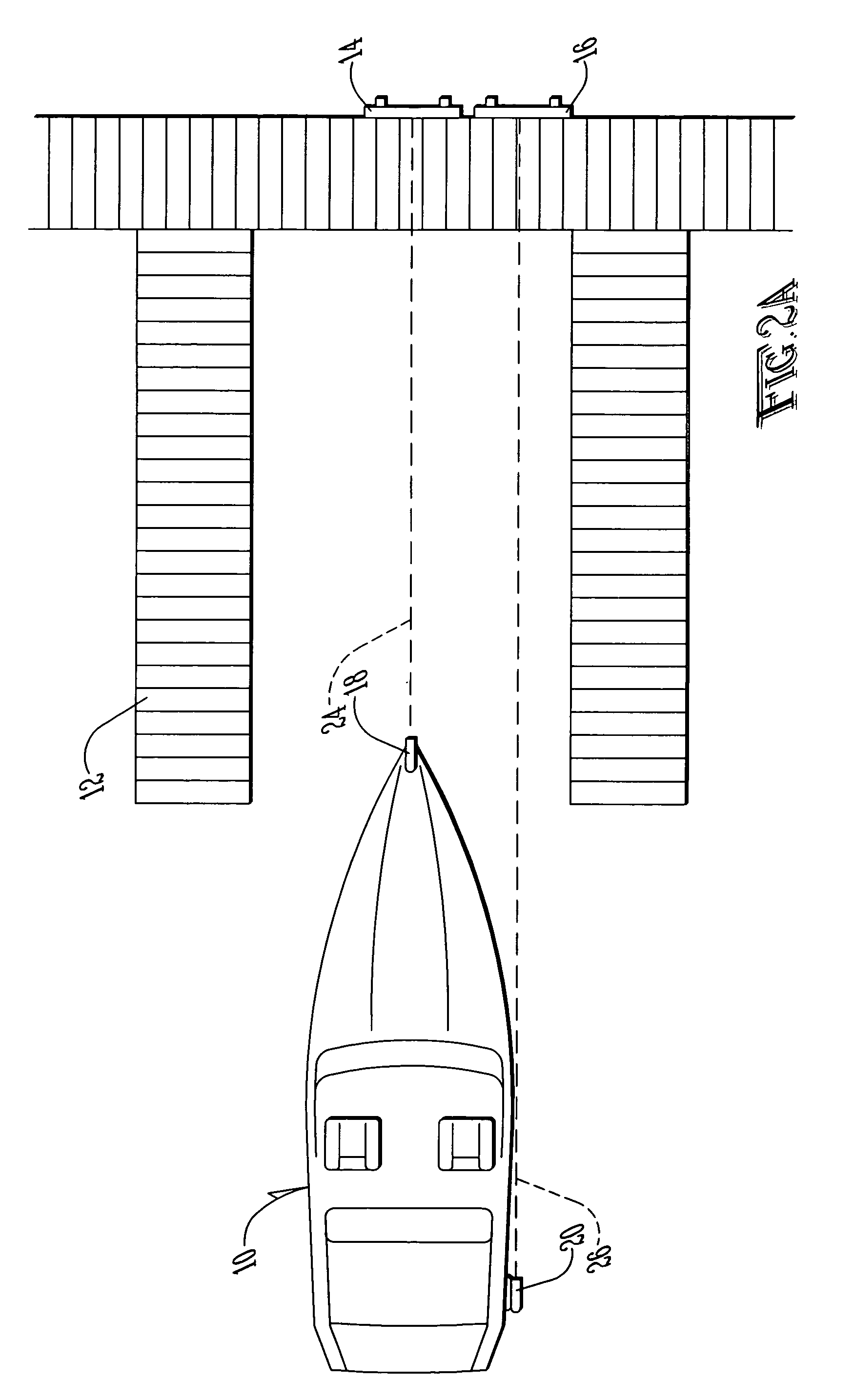
Both types of information are critical, since a failure to maintain alignment of the boat's stern may cause a crash even if the bow of the boat is perfectly oriented with respect to the dock, slip, or trailer.
As the pilot turns his or her head in an attempt to gather information about the position of the ship's stern, he or she is distracted at a critical time, which may cause the bow of the ship to fall out of alignment.
Even an experienced pilot may be unable to successfully guide a vessel into its dock or slip if, for example, an unexpected wind or current change were to occur at a critical moment.
The prior art includes numerous attempts to address these sorts of difficulties, none of which are wholly practical and feasible for all purposes and applications.
While this simple method of alignment may be sufficient for some purposes, such a method lacks any capability for independently aligning the rear portion of the vehicle, which may be important for reasons as described above.
The method would also be inadequate for the docking of watercraft, since the stern of such a vessel is, as already explained, subject to movement and rotation with respect to the bow from myriad forces acting on the vessel.
This alignment technique, like the one-emitter system described above, is insufficient for many applications because it includes no means by which the rear or stern of a vessel may be separately aligned.
Again, this system contains no means for separate alignment of the rear of the aircraft.
'767 does, unlike the previously discussed prior art, provide information about the position and velocity of the stern of a vessel independently from the bow of that same vessel, this system still suffers from significant limitations.
The two pulse range radar devices necessary in order to make this system operable are quite complex and expensive.
While the cost of such devices might be feasible when the docking vessel is a large, ocean-going vessel carrying a massive and valuable cargo, such a system could not be feasible when the pulse range radar devices represent a significant cost with respect to, and perhaps even greater than, the cost of the vessel itself.
Thus this device would be impractical at any dock or slip facility that did not maintain permanent personnel for such purpose.
Again, this would make this device impractical for most docks or slips used by all but the largest commercial vessels.
In any case, such systems are very expensive, and require considerable training and skill for operation due to their complexity.
They are thus, like the LIDAR systems described above, impractical for many important applications, including the vast majority of watercraft intended for personal use.

Method used


Image

  • Vehicle positioning apparatus
  • Vehicle positioning apparatus
  • Vehicle positioning apparatus

Examples


Embodiment Construction

[0032]With reference to FIG. 1, the preferred embodiment of the present invention may now be described. Watercraft 10 afloat in body of water 11 is to be brought into slip 12. (Certain details of slip 12 have been omitted for clarity.) In the preferred embodiment, watercraft 10 is a yacht, cruiser, houseboat, or similar watercraft that is typically moored at docks or slips designed for boats employed for personal rather than commercial use. It should be noted, however, that the invention is not so limited, and the present invention may in fact be used in connection with any sort of vehicle that must be navigated into, out of, or through a small or enclosed space. In addition, while slip 12 is shown as used in connection with the preferred embodiment, alternative embodiments may replace slip 12 with a dock, boat trailer, or any other limited space into which a vehicle may be maneuvered for various purposes.

[0033]Mounted on watercraft 10 are first emitter 18 and second emitter 20. In ...


PUM


Abstract

A vehicle positioning apparatus is shown and described. The positioning apparatus is adaptable for the guidance of a vehicle into a limited space, such as in the case of a boat approaching a dock, slip, or trailer. The vehicle includes two emitters, producing two images reflected to the operator of the vehicle. The emitters are spaced from each other in such a manner that the operator may determine direction, orientation, and other critical parameters of the vehicle during approach to the limited space by viewing of the reflected images. Targets may be employed to enhance the image seen by the operator.

Description

BACKGROUND OF THE INVENTION[0001]The present invention relates to vehicle positioning systems, and in particular to vehicle position systems using emitters positioned on the vehicle and with respect to each other so as to provide a simple and effective means of directing the vehicle into, out of, or through a small space.[0002]Since ancient times, it has been recognized that the control of a ship during docking is a task that requires great skill of the ship's helmsman and crew. Such skill is required because of the many and varied factors that can influence the motion of a vessel on the water. Currents in the water, waves, and winds exert significant effects on vessels attempting to dock. Other factors include the condition of the vessel; the size and shape of the vessel's hull; the position of the helm on the vessel; the nature, number, and location of propulsion systems on the vessel; the size and configuration of the dock or slip used; and the amount and nature of involvement fr...

Claims


Application Information

Patent Timeline
Patent Type & Authority Patents(United States)
IPC IPC(8): B60Q1/00B63B49/00G05D1/02G08G3/02
CPCB63B49/00G05D1/0206G08G3/02
Inventor WORTSMITH, JOE W.
Owner WORTSMITH JOE W
Why Eureka
Try Eureka