Lens, optical head, optical information writing/reading apparatus and optical information recording medium writing/reading method

a technology of optical information and writing/reading apparatus, which is applied in the field of optical head, optical head, optical disk writing/reading apparatus and optical disk writing/reading method, can solve the problems of detection signal deterioration and low utilization efficiency of laser light emitted from semiconductor lasers, and achieve the effect of extending the range of phase selection

Inactive Publication Date: 2006-02-07
PANASONIC CORP +1
View PDF32 Cites 67 Cited by
  • Summary
  • Abstract
  • Description
  • Claims
  • Application Information

AI Technical Summary

Benefits of technology

[0022]In view of the problems of the conventional optical head described above and it is an object of the present invention to reduce vari...

Problems solved by technology

Furthermore, in the above-described conventional configuration, luminous flux that passes through the intermediate area when writing/reading a DVD optical disk does not contribute to writing or reading, causing a problem that t...

Method used


Image

  • Lens, optical head, optical information writing/reading apparatus and optical information recording medium writing/reading method
  • Lens, optical head, optical information writing/reading apparatus and optical information recording medium writing/reading method
  • Lens, optical head, optical information writing/reading apparatus and optical information recording medium writing/reading method

Examples


embodiment 1

[0138]FIG. 11 illustrates a configuration of an optical system of an optical head according to Embodiment 1 of the present invention. The configuration shown in the same drawing is the same as the configuration of the optical head of the conventional example shown in FIG. 8 except the objective lens 20 and the same components as those in FIG. 8 are assigned the same reference numerals and explanations thereof will be omitted. A photo detector 4 in FIG. 11 is applicable as the photoreception element of the optical head of the present invention and a read signal circuit 10 in FIG. 11 is applicable as the circuit of the optical information writing / reading apparatus of the present invention. The photo detector 4 is the means of receiving reflected light from the optical disk 7 and converting the reflected light to an electric signal and the read signal circuit 10 is a circuit that distinguishes the type of the optical disk 7 and selectively reads information from the electric signal.

[01...

embodiment 2

[0150]FIG. 12 illustrates a configuration of an optical system of an optical head according to Embodiment 2 of the present invention. The configuration shown in the same drawing is the same as the configuration of the optical head shown in Embodiment 1 of the present invention except the objective lens 21 and the same components as those in FIG. 11 are assigned the same reference numerals and explanations thereof will be omitted. FIG. 4 shows the objective lens 21 according to Embodiment 2.

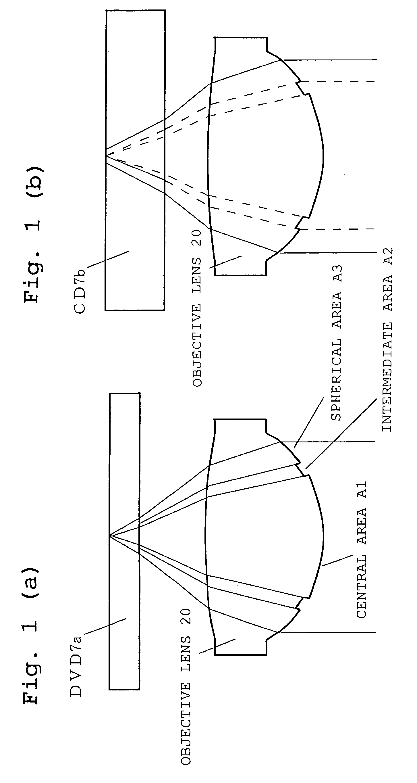
[0151]As shown in FIG. 4, what the objective lens 21 according to Embodiment 2 differs from the objective lens 20 shown in Embodiment 1 is that the surface on which the intermediate area A2 is set is a second surface which is the surface of the side facing the substrate and the thickness of the corresponding base material of the intermediate area A2.

[0152]In Embodiment 1, the intermediate area A2 is set on the side of the first surface, while in this Embodiment, setting the intermediate area A2 on...

embodiment 3

[0161]FIG. 13 illustrates a configuration of an optical system of an optical head according to Embodiment 3 of the present invention. The configuration shown in the same drawing is the same as the configuration of the optical head shown in Embodiment 1 of the present invention except the objective lens 22 and the same components as those in FIG. 11 are assigned the same reference numerals and explanations thereof will be omitted. FIG. 6 shows the objective lens 22 according to Embodiment 3.

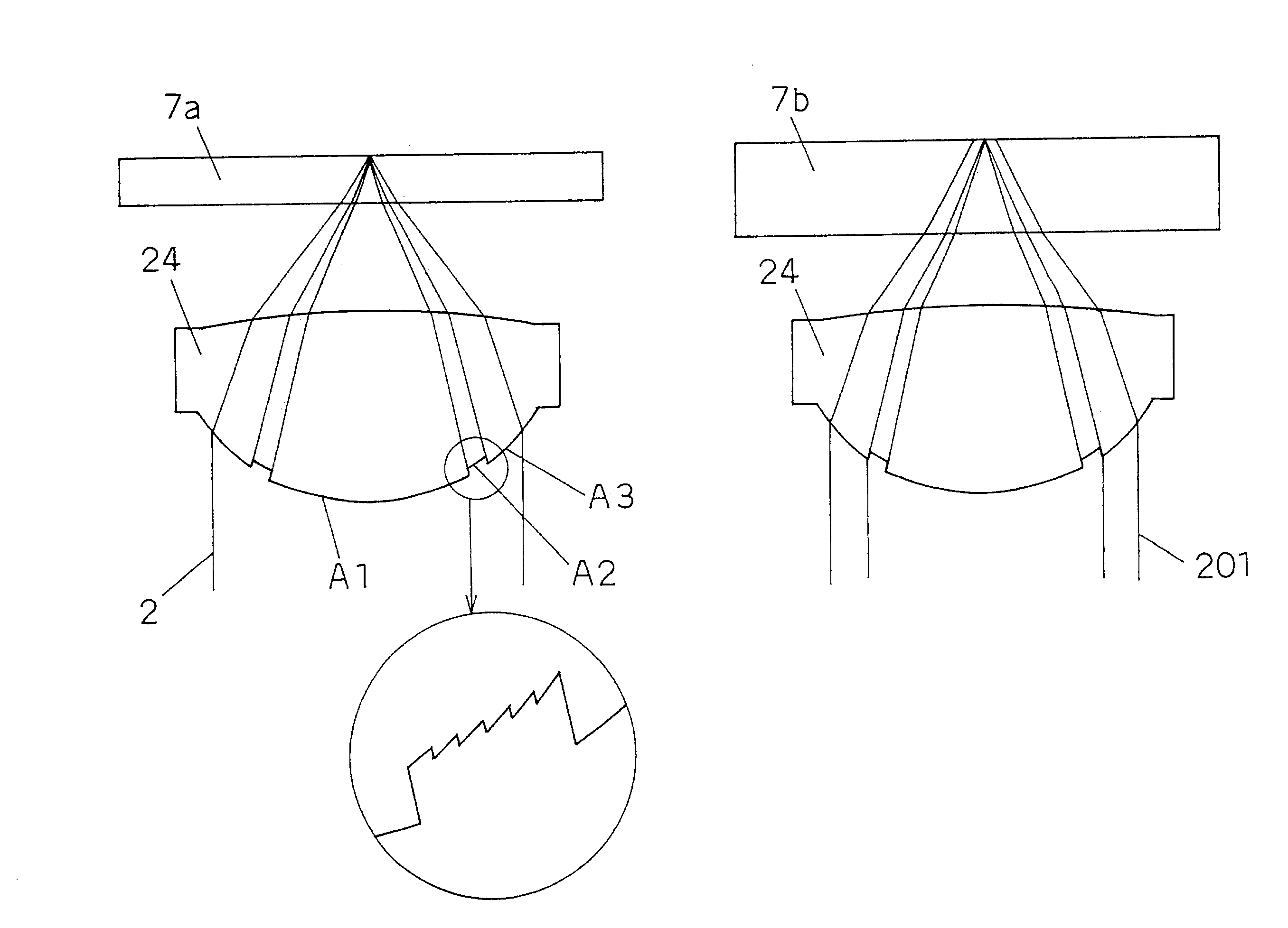
[0162]Here, what the objective lens 22 according to Embodiment 3 differs from the objective lens 21 shown in Embodiment 2 is that the phase of the central area A1 is shifted from the peripheral area A3 by 1 wavelength (DVD wavelength) with respect to the wavelength of the DVD and that the thickness of the corresponding base material of the intermediate area A2 is set to 1.2 mm and that outside NA of the intermediate area A2 is set to 0.46.

[0163]As is apparent from a comparison between FIG. 4 and F...


PUM


Abstract

Conventional lenses for DVD/CD compatible writing/reading are liable to CD jitter deterioration due to phase shifts in a central area.
Setting a corresponding base material thickness of an intermediate area of the circumference A2 to greater than 1.2 mm which is the base material thickness of the CD, that is, converging luminous flux that has passed through the intermediate area of the circumference A2 onto a farther place than the information recording surface of the base material thickness of the CD makes it possible to reduce jitter deterioration due to phase shifts. Further, it makes possible to provide a system with higher precision and higher reliability.

Description

[0001]THIS APPLICATION IS A U.S. NATIONAL PHASE APPLICATION OF PCT INTERNATIONAL APPLICATION PCT / JP00 / 06926.TECHNICAL FIELD[0002]The present invention relates to a lens, an optical head, an optical disk writing / reading apparatus and an optical disk writing / reading method.BACKGROUND ART[0003]An optical memory technology using optical disks as high density, high capacity storage media with pit-shaped patterns, is widening its applicability to digital audio disks, video disks, document file disks and data files, etc.[0004]According to this optical memory technology, information is recorded onto and reproduced from an optical disk via micro-focused light beams with high accuracy and reliability. This writing / reading operation solely depends on its optical system.[0005]The basic functions of the optical head, which is a major component of the optical system, are broadly grouped under convergence that forms micro spots of diffraction limits, focus control and tracking control of the above...

Claims


Application Information

Patent Timeline
IPC IPC(8): G02B5/18G11B7/1374G11B7/00G11B7/135
CPCG11B7/1353G11B7/1367G11B7/1374G11B7/139G11B7/13922G11B7/1378G11B2007/13727G11B2007/0006G11B7/1372G11B7/1275G11B7/0943G11B20/10398G11B7/133G11B7/2403G11B2220/2545G11B2220/2562
Inventor HAYASHI, HIDEKIMIZUNO, SADAO
Owner PANASONIC CORP
Why Eureka
Try Eureka