
Velocity analysis on seismic data

Inactive Publication Date: 2006-02-07
WESTERNGECO LLC
View PDF15 Cites 3 Cited by
  • Summary
  • Abstract
  • Description
  • Claims
  • Application Information

AI Technical Summary

Benefits of technology

[0022]The present invention replaces the method of conventional stacking with a technique based on interpolation that can be performed very quickly on modern graphics computers.

Problems solved by technology

Stacking a line is a CPU intensive process that necessitates the use of large and powerful machines, especially if it is to be done in real time.

Method used


Image

  • Velocity analysis on seismic data
  • Velocity analysis on seismic data
  • Velocity analysis on seismic data

Examples


Embodiment Construction

[0031]The computer shown in FIG. 4 comprises a central processing unit (CPU) 10 provided with an input arrangement 11 and an output arrangement 12, for example including a display for displaying the results of the processing performed by the CPU 10. The computer has a program memory 13 which contains a computer program for controlling the operation of the CPU 10 to perform a seismic data processing method as described hereinafter. The computer also has a scratchpad memory 14 for temporarily storing data during operation of the CPU 10, including a three dimensional (3D) memory which cooperates with graphics processing software in the program memory 13 to perform graphics processing including interpolation. The computer therefore functions as a graphics computer, such as a Sun or Silicon Graphics workstation or a high end PC having sufficient memory to store a large “cube” of data and a 3D graphics card with texture mapping which supports the OpenGL language from Silicon Graphics to p...


PUM


Abstract

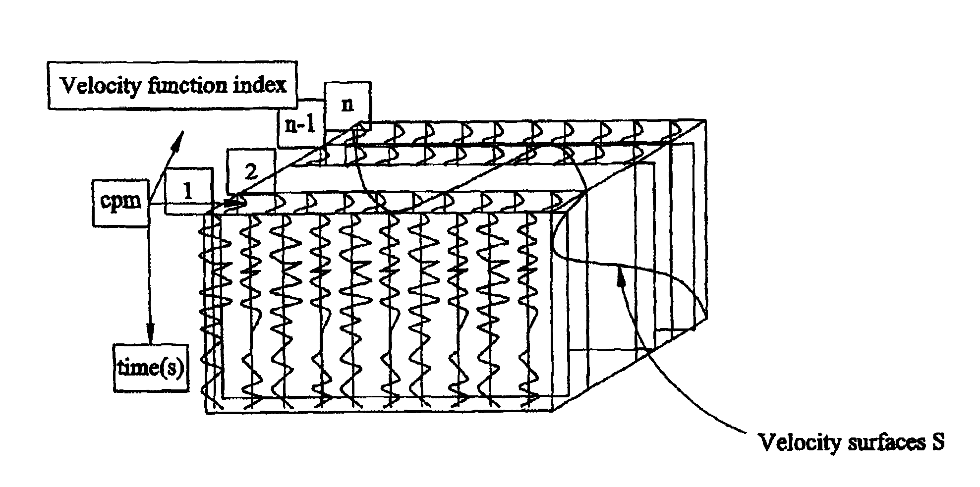
A number of seismic stacks are precomputed (20) for known velocity fields. The velocity fields are chosen to span the range of velocities of interest. The stacks are then arranged (21) in the 3D memory of a graphics computer (10–14) using time and position as first dimensions and the index of the velocity field as the last dimension. In such 3D space, any velocity field to be used for stacking appears as a surface (S) within a volume. Projecting the seismic stacks onto that surface provides the seismic line stacked for the velocity field of interest.

Description

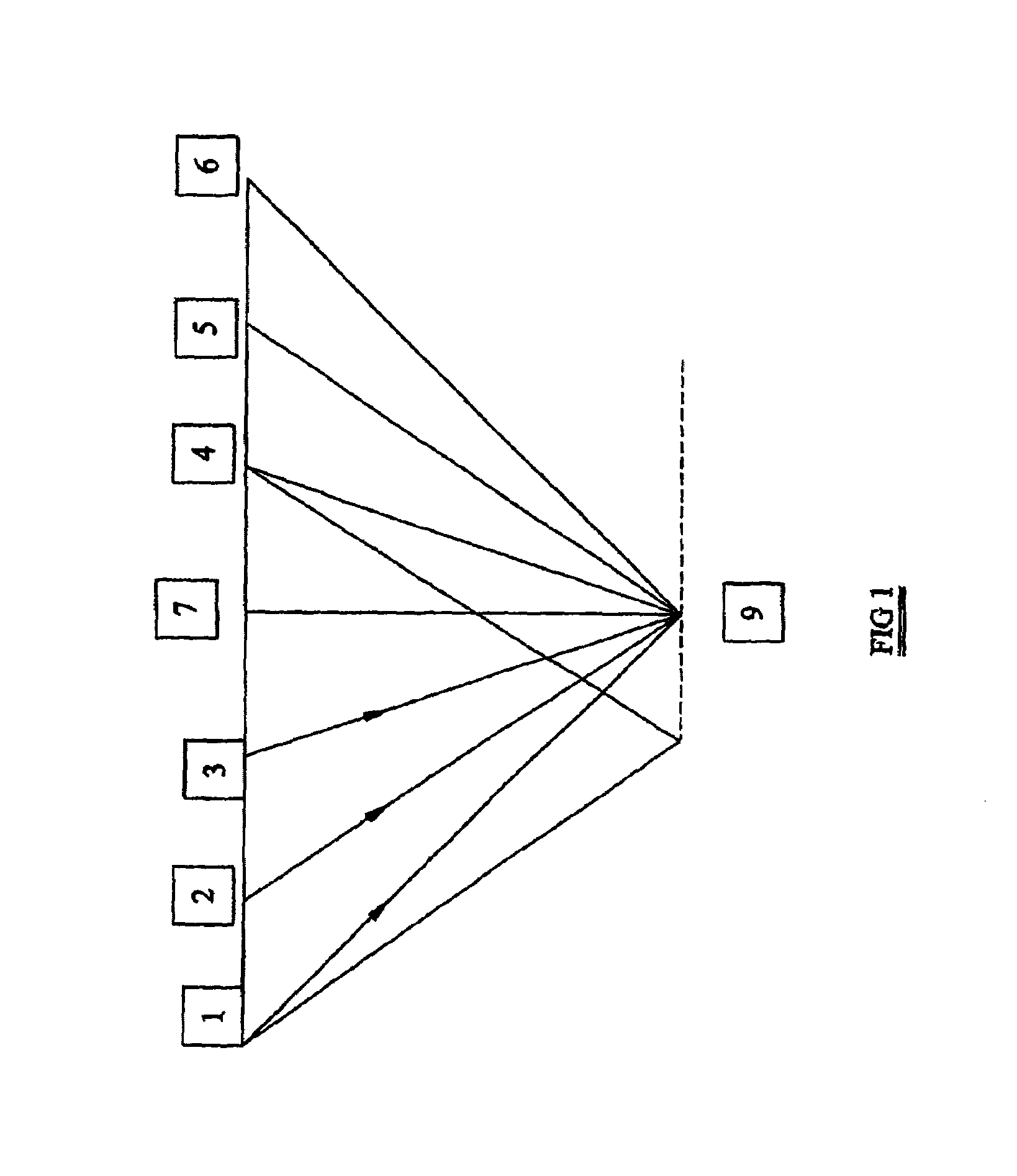
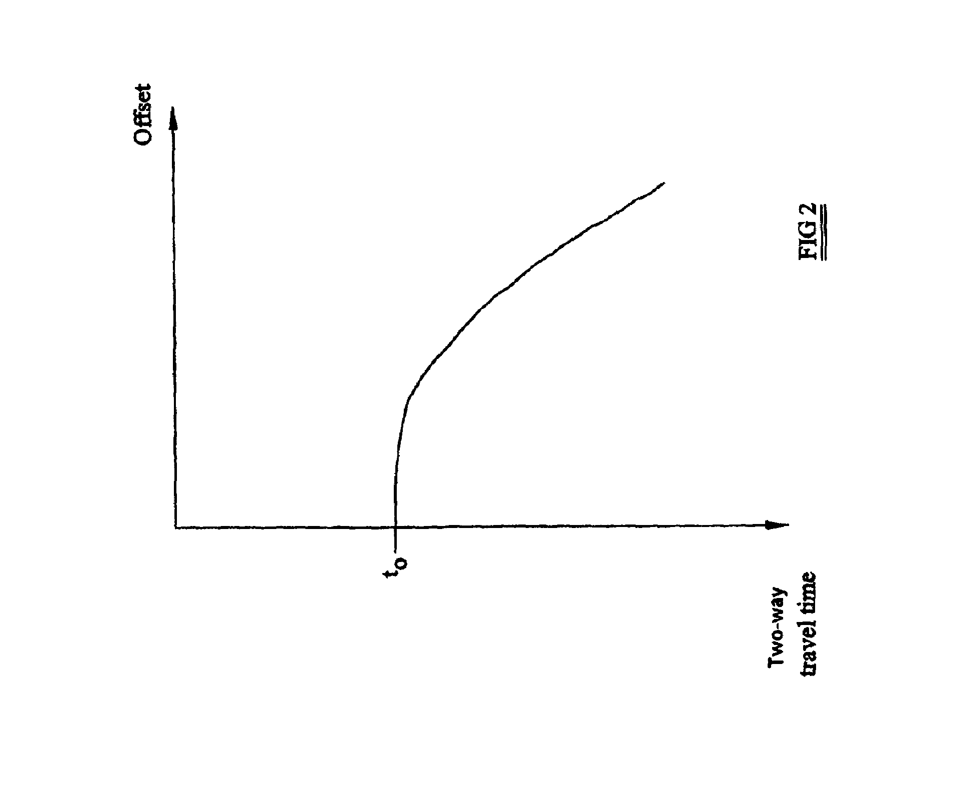
BACKGROUND OF THE INVENTION[0001]1. Field of the Invention[0002]The present invention relates to a method of processing seismic data and provides a technique for computing a stacked line by interpolation between known stacks.[0003]2. Description of the Related Art[0004]Seismic data are collected using an array of seismic sources and seismic receivers. The data may be collected on land using, for example, explosive charges as sources and geophones as receivers. Alternatively, the data may be collected at sea using, for example, airguns as sources and hydrophones as receivers. After the raw seismic data have been acquired, the reflected signals (known as traces) received by each of the receivers as a result of the process of actuation of a seismic energy source are processed to form a subsurface image. The processing includes the steps of accounting for the separation (known as offset) between sources and receivers and summing related traces together to increase signal / noise ratio (a ...

Claims


Application Information

Patent Timeline
Patent Type & Authority Patents(United States)
IPC IPC(8): G01V1/34G01V1/28G01V1/30G01V1/36
CPCG01V1/303G01V1/362G01V2210/52
Inventor BERNTH, HENRIKDAUBE, FRANCOIS
Owner WESTERNGECO LLC
Learn More