Image forming apparatus

a technology of image forming apparatus and forming tube, which is applied in the direction of electrographic process apparatus, instruments, optics, etc., can solve the problems of large amount of electric power, inability to uniformly electrify or eliminate static, and reduced resistan

Inactive Publication Date: 2006-02-07
CANON KK
View PDF13 Cites 4 Cited by
  • Summary
  • Abstract
  • Description
  • Claims
  • Application Information

AI Technical Summary

Benefits of technology

[0028]Thus, the present invention has been made in view of the current situation described above, and the object thereof is to provide an image forming apparatus capable of forming a satisfactory image without being influenced by the change of resistance of a transferring member, the environmental change of resistance of a transferring material and the like.

Problems solved by technology

However, the corona electrifier has problems such that ozone is emitted during electrification or static elimination, and a large amount of electric power is required, and therefore currently a conductive contact-type electrifier having the reduced amount of ozone emission and being capable of electrification with a small amount of electric power is often used.
However, the roller-shaped transferring member is adjusted in resistance to keep the resistance within the middle resistance range by dispersing usually a conductive filler imparting conductivity such as carbon black or a metal oxide in a polymer elastomer material, but the uniformity of dispersion is not adequate from a production viewpoint, and circumferential resistance unevenness (hereinafter referred to as circumferential unevenness) occurs, resulting in a problem such that uniform electrification or static elimination is impossible.
However, even the transferring member having ionic conductivity has the following problems.(1) The resistance changes significantly depending on environments (absolute water amount (weight of water contained in 1 kg of air)).(2) The resistance increases if currents of same polarity are continuously applied.(3) The resistance may decrease due to an increase in temperature within a main body even in the same environment, and transfer failure associated with the decrease in resistance may occur depending on the environment (absolute water amount (weight of water contained in 1 kg of air)) and the transferring material as a transfer object.
However, this configuration has an effect of inhibiting an increase in resistance with duration, but has limitations in prolonging a life.
With these disclosed techniques alone, however, there have been cases where a proper transferring bias cannot be supplied when the resistance value of the transferring roller is considerably deviated from the normal resistance value.
However, this publication does not disclose countermeasures as to the type of transfer object, the resistance change for the absolute water amount of the transfer object, and the resistance change for the absolute water amount of the transferring material.
In addition, for countermeasures for the transfer object, Japanese Patent Application Laid-Open No. 2001-109281 discloses a technique in which a set voltage of transferring voltage is determined from an impedance detected when the transfer object enters a transfer nip, but this technique requires control in an edge image marginal portion, and therefore makes it difficult to enhance a speed.
In addition, the resistance of the transferring material P changes depending on the environment where the image forming apparatus is placed, particularly on the absolute water amount, and it is known that the above phenomena also vary depending on the type of transferring material P, and therefore the above problems can not be sufficiently solved with the prior art described in the example of the conventional technique.
It is apparent that if a conductive member having an ionically conductive polymer excellent in resistance stability particularly under a fixed environment and excellent in mass production resistance stability but poor in environmental resistance stability is employed for the transferring roller, countermeasures against the environmental change of resistance of the transferring roller are important, from the environmental change of resistance in FIG. 10 and the change of resistance in the main body shown in FIG. 5.

Method used


Image

  • Image forming apparatus
  • Image forming apparatus
  • Image forming apparatus

Examples


first embodiment

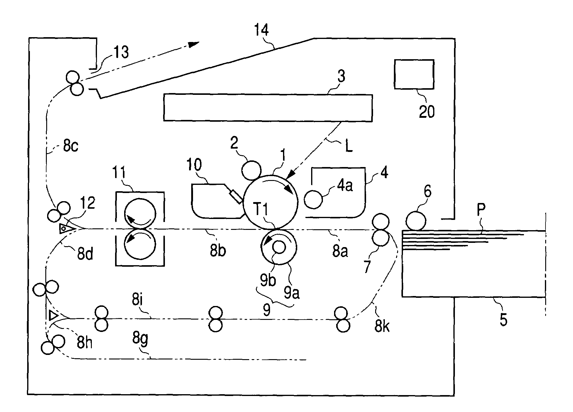
[0047]FIG. 1 shows an outlined configuration of an image forming apparatus according to the present invention, reference numeral 1 denotes a photosensitive drum being an image bearing body. Here, this photosensitive drum 1 is rotated in a clockwise direction at a predetermined circumferential speed (process speed) as shown by the arrow, and is electrified by electrification means 2 being a contact electrification member so that its circumferential surface has a predetermined polarity and potential (first electrification).

[0048]Reference numeral 3 denotes a laser beam scanner as image exposing means for outputting a laser beam L on / off-modulated according to image information inputted from an external apparatus such as an image scanner or computer (not shown) to scan-expose the electrified surface on the photosensitive drum 1, and a static latent image corresponding to desired image information is formed on the photosensitive drum 1 by the scan exposure by the laser beam scanner 3.

[0...

second embodiment

[0097]the present invention will now be described.

[0098]FIG. 9 shows an outlined configuration of an image forming apparatus according to this embodiment, the image forming apparatus has first to fourth image forming portions Pa to Pd placed side by side in its main body, toner images of different colors are formed through processes of latent image development, development and transfer in the image forming portions Pa to Pd.

[0099]Specifically, the image forming portions Pa to Pd comprise their own photosensitive drums 3a to 3d, respectively, toner images of different colors are formed on the photosensitive drums 3a to 3d. In addition, an intermediate transferring body 50 being a second image bearing body is placed in proximity to the photosensitive drums 3a to 3d, and a yellow toner image of first color on the photosensitive drum 3a is transferred to the intermediate transferring body 50 (first transfer) by a transferring bias applied to a first transferring roller 24a by a high-vol...


PUM


Abstract

An image forming apparatus including an image bearing body bearing an image, a transferring member being capable of contacting the image bearing body and transferring an image on the image bearing body to a transferring material when a voltage is applied thereto, and control portion for controlling the voltage applied to the transferring member,
wherein the control portion determines the value of a reference voltage required for passing a current of a predetermined value appropriate to the type of transferring material through the transferring member contacting the image bearing body, and applies to the transferring member a transferring voltage of a value determined by adding to the reference voltage value an addition voltage value appropriate to the type of transferring material at the time when the image is transferred to the transferring material.

Description

BACKGROUND OF THE INVENTION[0001]1. Field of the Invention[0002]The present invention relates to an image forming apparatus employing an electrophotography process or electrostatography process, and particularly to control of a transferring voltage applied to a transferring material when a developer image is transferred to the transferring material.[0003]2. Related Background Art[0004]Conventionally, in an image forming apparatus employing an electrophotography process or electrostatography process, a static latent image formed on an image bearing body is developed by a developer to form a developer image, followed by transferring the developer image on the image bearing body to a transferring material. When a toner image being the developer image is transferred onto the transferring material in this way, a transferring voltage is applied to the back surface of the transferring material to electrify the transferring material, and as means for electrifying the transferring material i...

Claims


Application Information

Patent Timeline
Patent Type & Authority Patents(United States)
IPC IPC(8): G03G15/16G03G15/00G03G15/01
CPCG03G15/1675
Inventor TOMIZAWA, TAKESHI
Owner CANON KK
Why Eureka
Try Eureka