Automatic calibration system for computer-aided surgical instruments

a computer-aided surgery and automatic calibration technology, applied in the direction of testing/calibration of speed/acceleration/shock measurement devices, sensors, diagnostics, etc., can solve the problems of inexperienced users, dramatic consequences of misrepresentation of instruments with respect to patients' bodies, and the required calibration maneuver may take a few minutes to an inexperienced user, etc., to facilitate calibration, facilitate use, and ensure accuracy

Inactive Publication Date: 2006-02-07
ORTHOSOFT ULC
View PDF18 Cites 154 Cited by
  • Summary
  • Abstract
  • Description
  • Claims
  • Application Information

AI Technical Summary

Benefits of technology

[0008]It is an aim of the present invention to provide a method for automatically calibrating surgical instruments which is simple and rapid in use and which produces a calibration of constant precision to facilitate the calibrating.

Problems solved by technology

A misrepresentation of the instrument with respect to the patient's body may have dramatic consequences and may even be fatal to the patient.
Although the axial-conical calibration method is simple, the required maneuvers of calibration may take a few minutes to an inexperienced user and the position calculator may require to repeat the maneuvers if they are judged as being unsatisfactory.
The instruments are subject to frequent manipulations during surgery, and thus, having sensors or detectable devices thereon involves the possibility that the position of these sensors or detectable devices is altered, whereby precision is lost in the space representation of the instrument.

Method used


Image

  • Automatic calibration system for computer-aided surgical instruments
  • Automatic calibration system for computer-aided surgical instruments
  • Automatic calibration system for computer-aided surgical instruments

Examples


Embodiment Construction

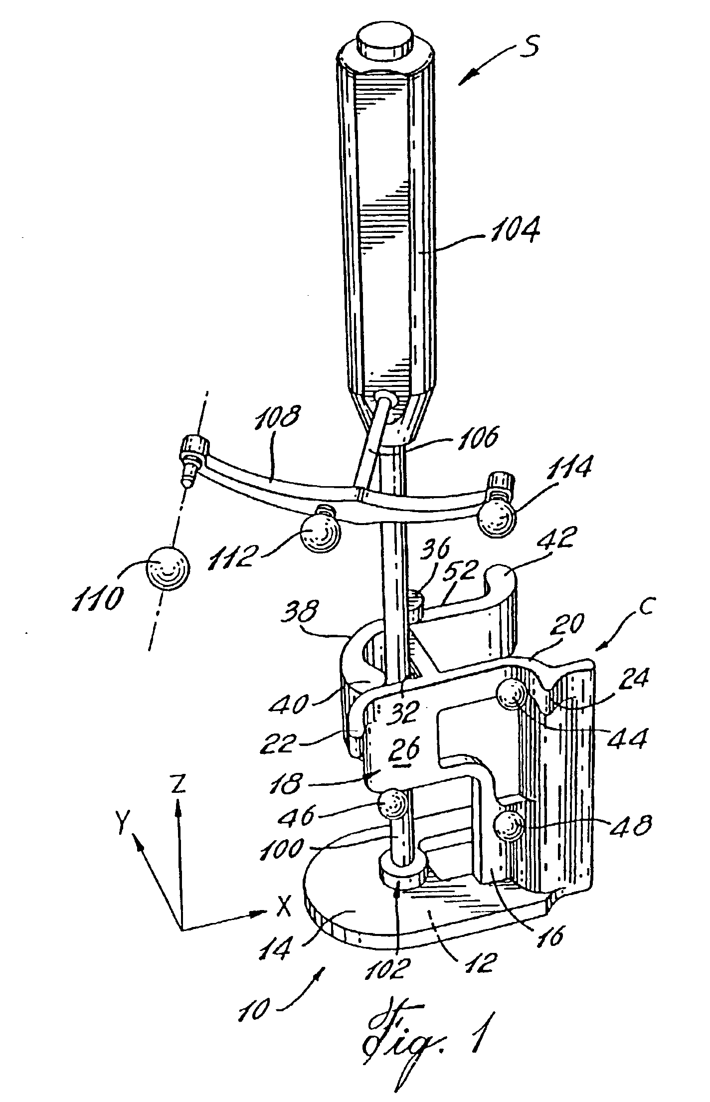
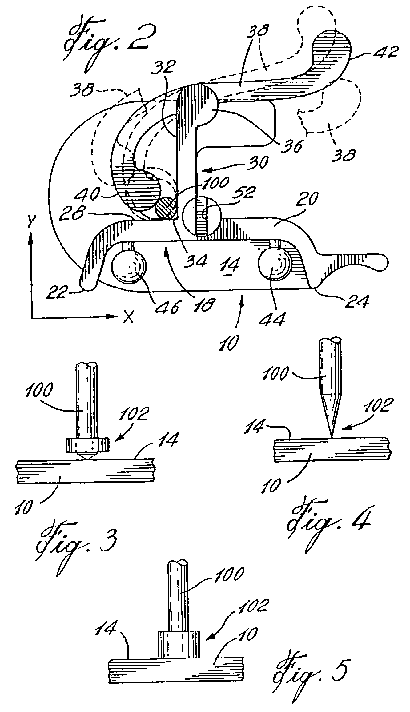
[0023]Referring to FIG. 1, there is shown a calibration base C supporting a surgical instrument S. The calibration base C comprises a base plate 10 having a bottom flat surface 12. The base plate 10 also defines an XY plane 14. For clarity purposes, XYZ axes have been added to the drawings in order to clearly identify the space orientation of planar elements. For instance, the XY plane 14 is planar with respect to the XY axes provided therewith. Also, it is noted that the calibration base C generally consists in a material which must be able to sustain several cycles of autoclave sterilization, such as a stainless steel. Some elements of the calibration base C will require to be made of other materials and will be identified herein as such.

[0024]A vertical wall 16 extends perpendicularly from the XY plane 14 of the base plate 10. A first panel 18 projects from a top portion of the vertical wall 16 and shares a top edge surface 20 therewith. A first protrusion 22 and a second protrus...


PUM


Abstract

A system for automatic calibration of instruments (S) having varying cross-sectional dimensions within a predetermined range and having detectable elements (110, 112, 113, 114) thereon for computer-aided surgery, comprising a calibration base (C) having detectable elements (43, 44, 46, 48) secured thereto for detecting a position and an orientation thereof in space by sensors (204) connected to a position calculator (202). The calibration base is adapted to receive and to releasably secure a working shaft (100) of any of the instruments (S) and provides an abutting surface (14) for a tip (102) thereof in such a way that a position and orientation of the tip (102) of the instrument (S) secured therein is calculable when working shaft cross-section dimensions thereof are known. The position calculator (202) receives instrument data (214) and calibration data (218) from an operator through a user interface (206) and stores the instrument data (214) and calibration data (218) for subsequent calibrations.

Description

BACKGROUND OF THE INVENTION[0001]1. Field of the Invention[0002]The present invention relates to computer-aided surgery instrumentation and, more particularly, to the calibration thereof.[0003]2. Description of the Prior Art[0004]In computer-aided surgery, it is known to use surgical instruments detectable by positioning systems in order to have an on-screen representation of the instrument with respect to an operated part of a patient's body. It is readily understood that great amounts of precision and accuracy are required in the space positioning of the surgical instruments in order to obtain reliable representation of the operation. A misrepresentation of the instrument with respect to the patient's body may have dramatic consequences and may even be fatal to the patient. Thus, prior to computer-aided surgery, the instruments must be calibrated.[0005]One known method of calibrating is referred to as the axial-conical calibration. This method consists in achieving pre-determined ...

Claims


Application Information

Patent Timeline
Patent Type & Authority Patents(United States)
IPC IPC(8): A61B5/05G01B21/00A61B17/00A61B19/00
CPCA61B19/20A61B19/201A61B19/5244A61B2019/5483A61B2019/5255A61B2019/5268A61B2017/00725A61B34/20A61B90/10A61B90/11A61B2034/2055A61B2034/2068A61B2090/3983
Inventor JUTRAS SEBASTIENBROSSEAU ERICJANSEN HERBERT ANDREC DOT OVER OTE GABRIELAMIOT LOUIS-PHILIPPE
Owner ORTHOSOFT ULC
Why Eureka
Try Eureka