Circuit board embedded inductor

Active Publication Date: 2006-02-14
QORVO US INC
View PDF5 Cites 98 Cited by
  • Summary
  • Abstract
  • Description
  • Claims
  • Application Information

AI Technical Summary

Problems solved by technology

The costs associated with a state of the art switching power supply include input and output filter inductors, which can account for a large fraction of the total cost in the bill of materials.

Method used


Image

  • Circuit board embedded inductor
  • Circuit board embedded inductor
  • Circuit board embedded inductor

Examples


Embodiment Construction

[0011]The embodiments set forth below represent the necessary information to enable those skilled in the art to practice the invention and illustrate the best mode of practicing the invention. Upon reading the following description in light of the accompanying drawing figures, those skilled in the art will understand the concepts of the invention and will recognize applications of these concepts not particularly addressed herein. It should be understood that these concepts and applications fall within the scope of the disclosure and the accompanying claims.

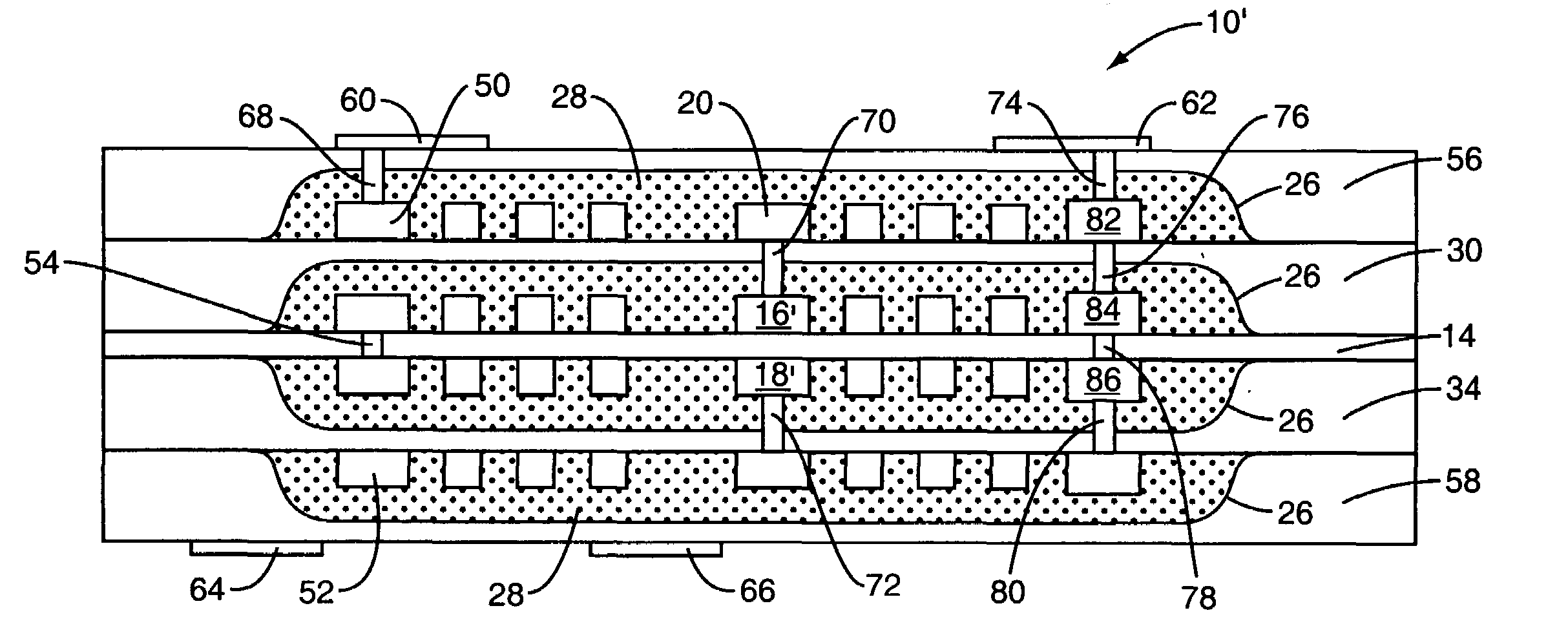
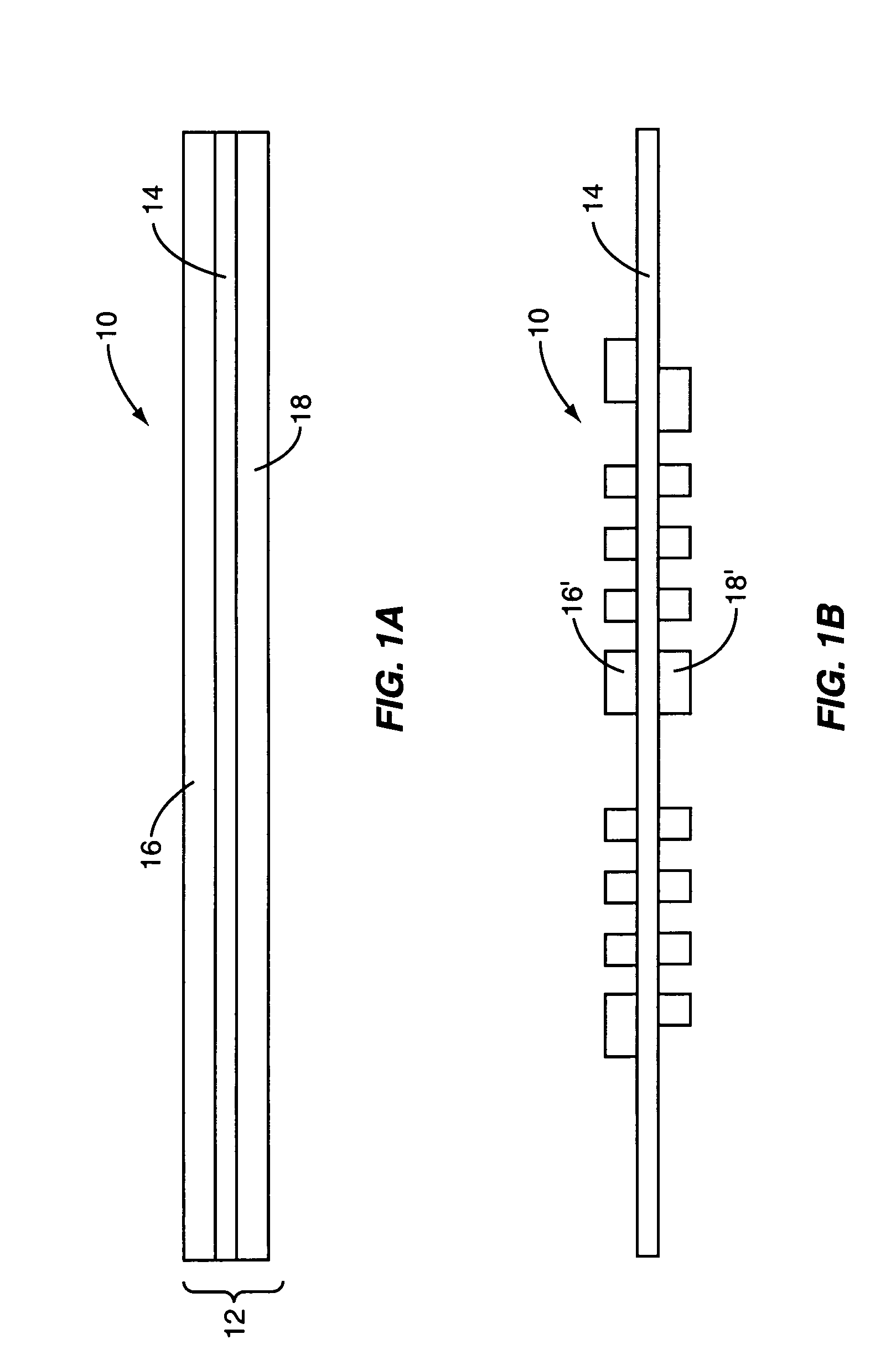
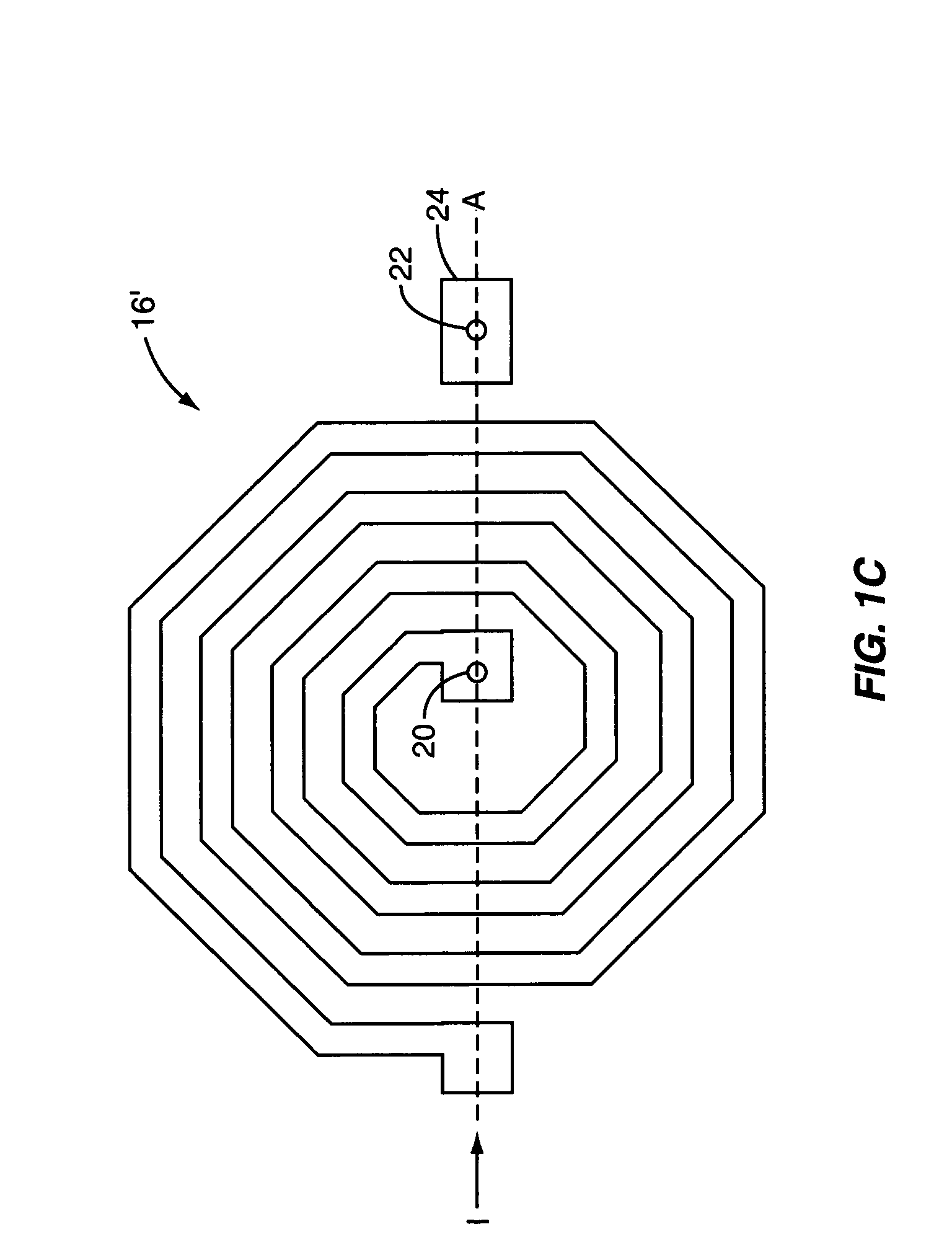
[0012]FIGS. 1A–1H illustrate a circuit board 10 including an inductor embedded within the circuit board 10 at sequential stages in during manufacture. Initially, the circuit board 10 begins as a core structure 12, which includes a dielectric core layer 14, a metal layer 16 on an upper surface of the dielectric core layer 14, and a metal layer 18 on a bottom surface of the dielectric core layer 14. The dielectric core layer 14 may ...


PUM

PropertyMeasurementUnit
thickaaaaaaaaaa
diameteraaaaaaaaaa
temperatureaaaaaaaaaa

Abstract

A circuit board having an embedded inductor and a process for making the circuit board is provided. In general, the process begins by providing a core structure including a dielectric core layer and a first metal layer on a top surface of the dielectric core layer. The first metal layer is etched to form first inductor windings. A material, such as an epoxy material, including magnetic filler material is deposited over the first inductor windings. Thereafter, a prepreg layer is placed over and attached to the material deposited over the first inductor windings to form the circuit board having the embedded inductor.

Description

FIELD OF THE INVENTION[0001]The present invention relates to circuit boards, and more particularly relates to a circuit board having an embedded inductor.BACKGROUND OF THE INVENTION[0002]Radio frequency (RF) power control in mobile terminals such as mobile telephones and the like may be implemented or augmented using a DC-DC converter, or switching power supply, to vary the voltage supplied to a power amplifier in the transmit chain of the mobile terminal in order to maintain high efficiency in the power amplifier. The costs associated with a state of the art switching power supply include input and output filter inductors, which can account for a large fraction of the total cost in the bill of materials. The application of this technology is further compounded by the physical size of the inductors, and the printed circuit board area that must be dedicated to the placement of the inductors. Accordingly, there remains a need for a low cost inductor requiring a minimum amount of area ...

Claims


Application Information

Patent Timeline
Patent Type & Authority Patents(United States)
IPC IPC(8): H01F7/06
CPCH01F17/0013H05K1/165H01F2017/002H01F2017/048H05K3/4626Y10T29/4902H05K3/4655H05K2201/0187H05K2201/0209H05K2201/086H05K3/4652
Inventor DENING, DAVIDDORN, STEVESHAH, MILINDRAO, YANGKAY, MICHAELJORGENSON, JON
Owner QORVO US INC
Why Eureka
Try Eureka