Anti-vibration support for steam generator heat transfer tubes and method for making same

a technology of anti-vibration support and steam generator, which is applied in the direction of stationary tubular conduit assembly, steam boiler components, reactor fuel elements, etc., can solve the problems of large structure, inability to effectively restrain tube vibrations, and gaps between heat exchanger tubes and high-bars, so as to achieve convenient installation and substantially eliminate vibration damage

Inactive Publication Date: 2006-02-14
BABCOCK & WILCOX CANADA LIMITED
View PDF12 Cites 12 Cited by
  • Summary
  • Abstract
  • Description
  • Claims
  • Application Information

AI Technical Summary

Benefits of technology

[0009]The present invention is drawn to a new apparatus and method for eliminating the gap between tubes and their respective support tube support bars in a nuclear steam generator, whereby the tubes are disposed in the correct positions, and whereby fretting and vibration damage are substantially eliminated. The tube support bars are made of special bimetallic bars or strips. The tube support bar is made by taking a first flat elongated metallic bar and attaching it to a second flat metallic bar at specific intervals. The second flat metallic bar has a coefficient of thermal expansion greater than that of the first bar. The tube support bars are flat during manufacture and installation at a first temperature, such as room temperature. At a second, or operating temperature, higher than the first temperature, however, each support bar automatically forms a plurality of “hill-shape” springs. Such “hill-shaped” springs engage the adjacent tube, thereby eliminating the gap between the tube and its respective support. The springs are not formed at room temperature, thereby providing a suitable clearance to assure ease of installation of tubes, or, alternatively, making the support bar easy to install after the tubes are in place.
[0010]It is therefore an object of the present invention to provide a tube support bar which minimizes gaps between the tubes and the support bar.
[0011]A further object of the invention is to minimize flow induced vibration of the tubes in a steam generator, thereby extending the useful life of the tubes.
[0012]It is a still further object of the invention to provide a tube support bar which is easy to manufacture, install, or remove for replacement.

Problems solved by technology

Nuclear steam generators must be capable of handling large quantities of two-phase secondary coolant moving at high flow rates, and are therefore very large structures.
Similarly, gaps may exist between the heat exchanger tubes and the high-bars.
Flow of steam and water past the tube induces vibrations which may not be effectively restrained due to the inherent gap.
This in turn may reduce the tube life expectancy.
For a typical nuclear steam generator, this design requires the manufacture and assembly of a very, very large number of spring parts, so that it is difficult to apply the idea in practice.

Method used


Image

  • Anti-vibration support for steam generator heat transfer tubes and method for making same
  • Anti-vibration support for steam generator heat transfer tubes and method for making same
  • Anti-vibration support for steam generator heat transfer tubes and method for making same

Examples


Embodiment Construction

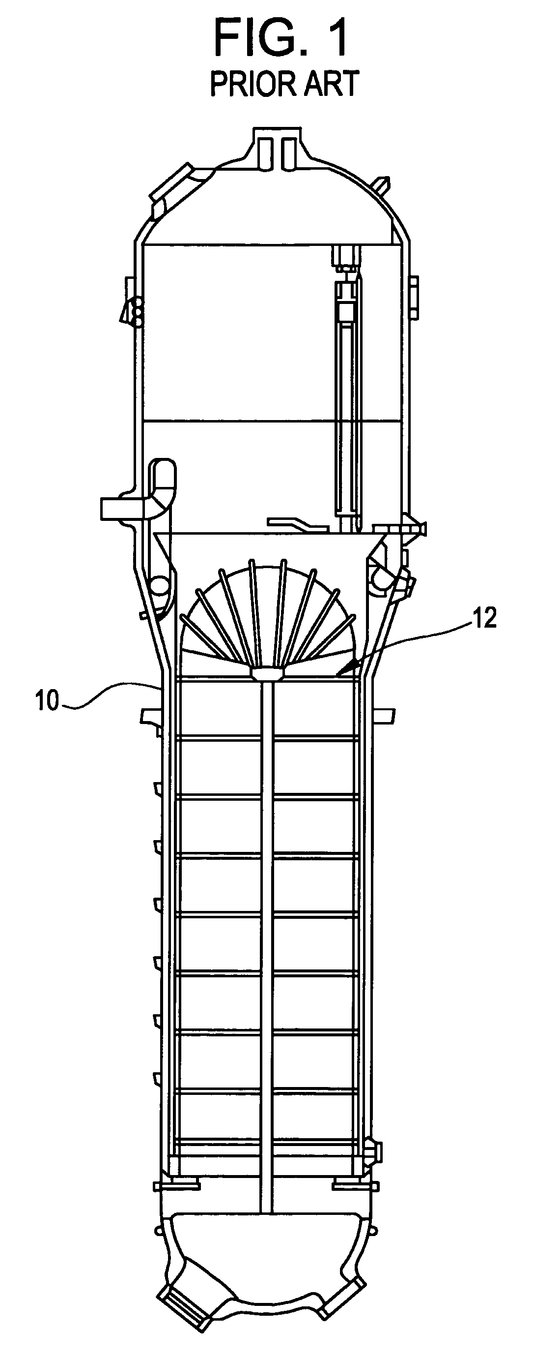
[0027]Referring now to the drawings, in which like reference numerals are used to refer to the same or functionally similar elements, FIG. 1 shows a nuclear steam generator 10 having a series of tube support bar arrays 12 at various points along its height for supporting a plurality of water tubes within the steam generator.

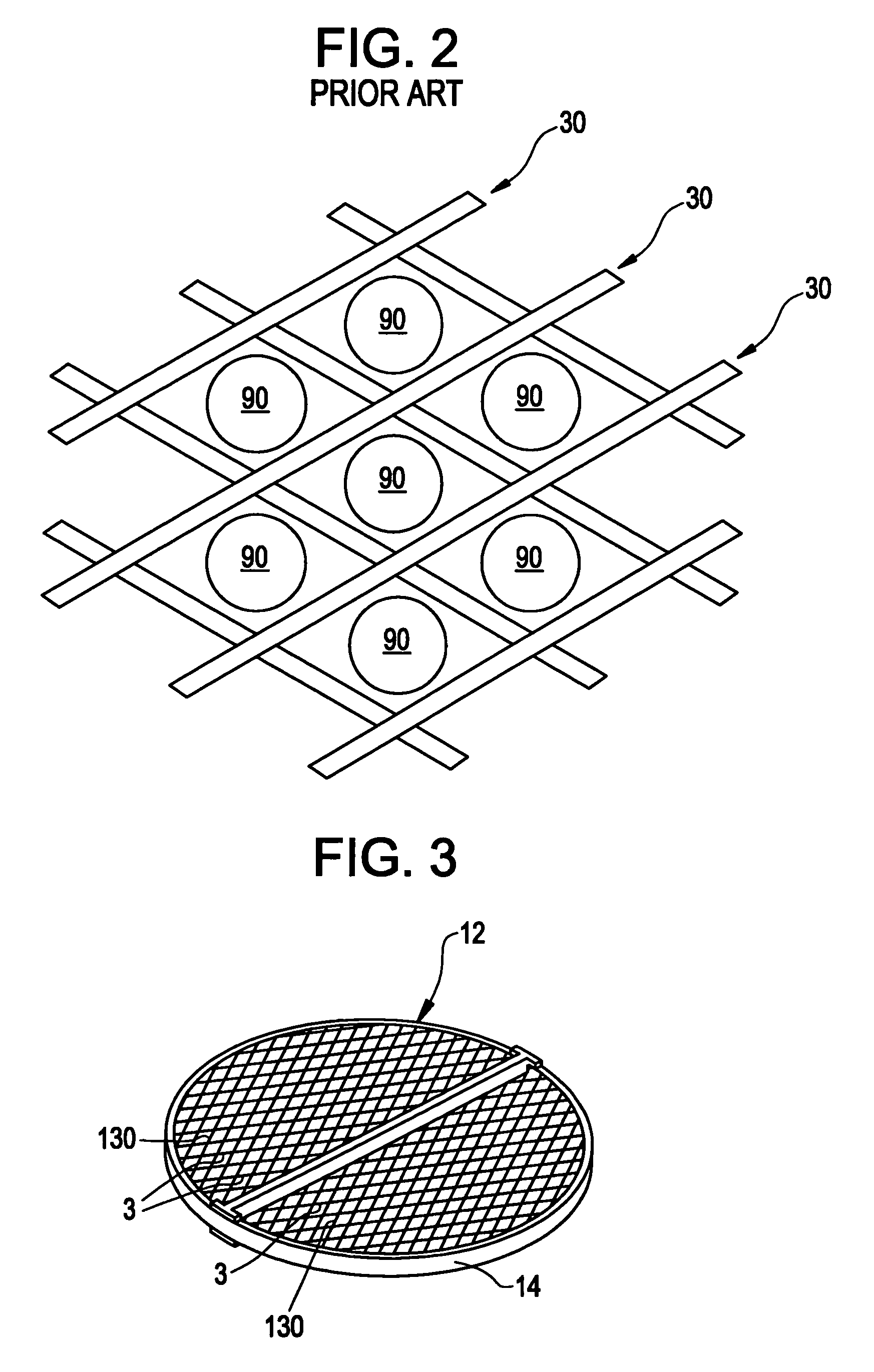
[0028]The tube support bar arrays 12 have a peripheral ring 14 supporting a series of high- and low-bars 3, 130, respectively, as shown in FIG. 3. The high- and low-bars 3, 130 are arranged parallel to one of two directions, with intersection angles of 60° and 120° where bars 3, 130 oriented in different directions cross each other.

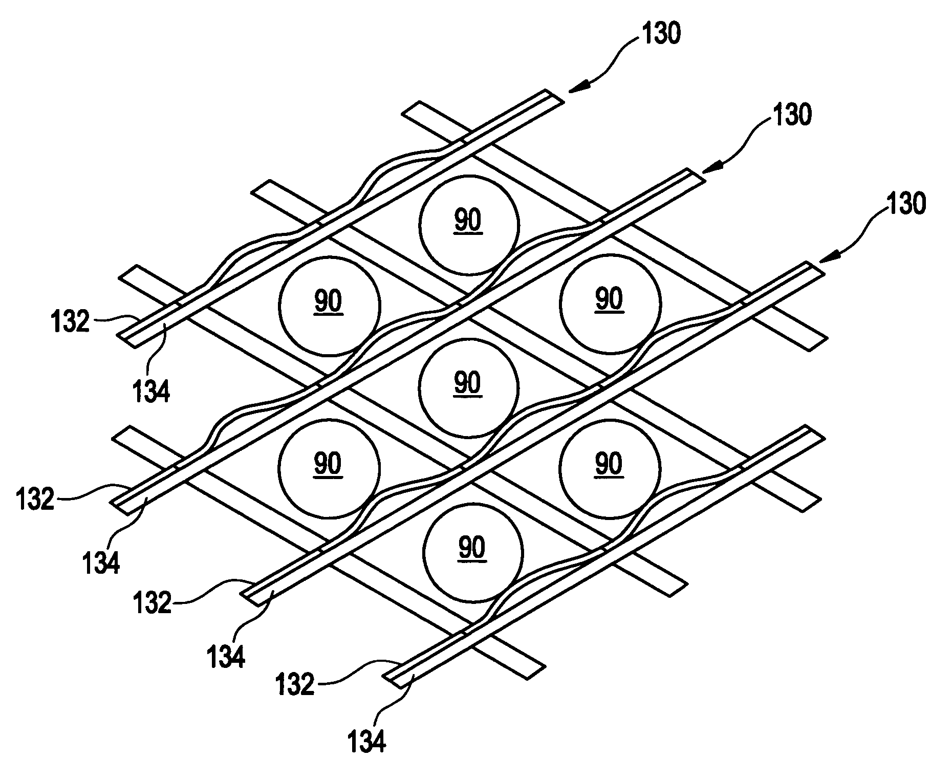
[0029]Referring to FIGS. 4–8, according to the subject invention, low-bar 130 is made of a relatively thin, preferably continuous, first strip or bar 132 secured to a relatively thick, preferably continuous, second strip or bar 134 via attachment 140. Attachment 140 is preferably made at uniformly spaced intervals 136 along and transve...


PUM

PropertyMeasurementUnit
thickaaaaaaaaaa
thickaaaaaaaaaa
diameteraaaaaaaaaa

Abstract

A tube support structure for heat transfer tubes in a steam generator has a plurality of tube support bars which are installed between the heat transfer tubes. At least one of the support bars has a first metal layer and a second metal layer. The first metal layer is preferably spot welded to the second metal layer at intervals. The first metal layer and second metal layer have different thermal expansion coefficients so that at room temperature the support bar is flat, and at the operating temperature of the steam generator the first layer forms a convex shape between the intervals to support the adjacent tube.

Description

FIELD AND BACKGROUND OF INVENTION[0001]The present invention relates generally to the field of nuclear power generation and in particular to a new and useful tube support bar for retaining and positioning water tubes within a nuclear steam generator.[0002]Water tubes for nuclear steam generators are typically 0.5 to 0.75 inches in diameter with a nominal wall thickness of 0.045 inches. In the once-through steam generator design, the tube bundle consists of straight tubes. In a recirculating steam generator, depicted in FIG. 1, the tube bundle is made up of U-tubes.[0003]In a pressurized water nuclear power station, steam generators, which are large heat exchangers, transfer heat, produced via nuclear reactions in the reactor core, from a primary water coolant to a secondary water coolant that drives the steam turbine. The primary coolant is pressurized, which allows the primary water coolant to be heated in the reactor core with little or no boiling. For example, in a light water re...

Claims


Application Information

Patent Timeline
Patent Type & Authority Patents(United States)
IPC IPC(8): G21C3/34F22B37/20F28D7/06F28F1/00F28F9/013
CPCF22B37/205F28D7/06F28F9/0132Y10T29/49391Y10T29/4935Y10T29/49393Y10T29/49364
Inventor SUN, NANSHENG
Owner BABCOCK & WILCOX CANADA LIMITED
Why Eureka
Try Eureka