Molded plastic flask

Active Publication Date: 2006-02-14
GRAHAM PACKAGING PET TECH
View PDF20 Cites 32 Cited by
  • Summary
  • Abstract
  • Description
  • Claims
  • Application Information

AI Technical Summary

Benefits of technology

[0002]Flask-shaped containers are conventionally employed in some liquid product applications, such as liquor. Such flask-shaped containers have opposed relatively closely spaced front and back walls, and opposed relatively widely spaced sidewalls that interconnect the side edges of the front and back walls. Vacuum assistance is conventionally employed to increase the filling speed of liquid into containers, including flasks. Such vacuum-assisted filling involves withdrawal of air from the container interior while simultaneously injecting liquid into the interior. Vacuum-assisted filling typically does not present a problem with flask-shaped containers of glass construction, for example, because the container walls are sufficiently rigid to withstand the internal vacuum forces during and after the filling operation. However, vacuum-assisted filling can present problems with flask-shaped containers of molded plastic construction because the large front and back walls of the container can deform inwardly under the internal vacuum forces. That is, internal va

Problems solved by technology

However, vacuum-assisted filling can present problems with flask-shaped containers of molded plastic construction because the large front and back walls of the container can defo

Method used


Image

  • Molded plastic flask
  • Molded plastic flask
  • Molded plastic flask

Examples


Embodiment Construction

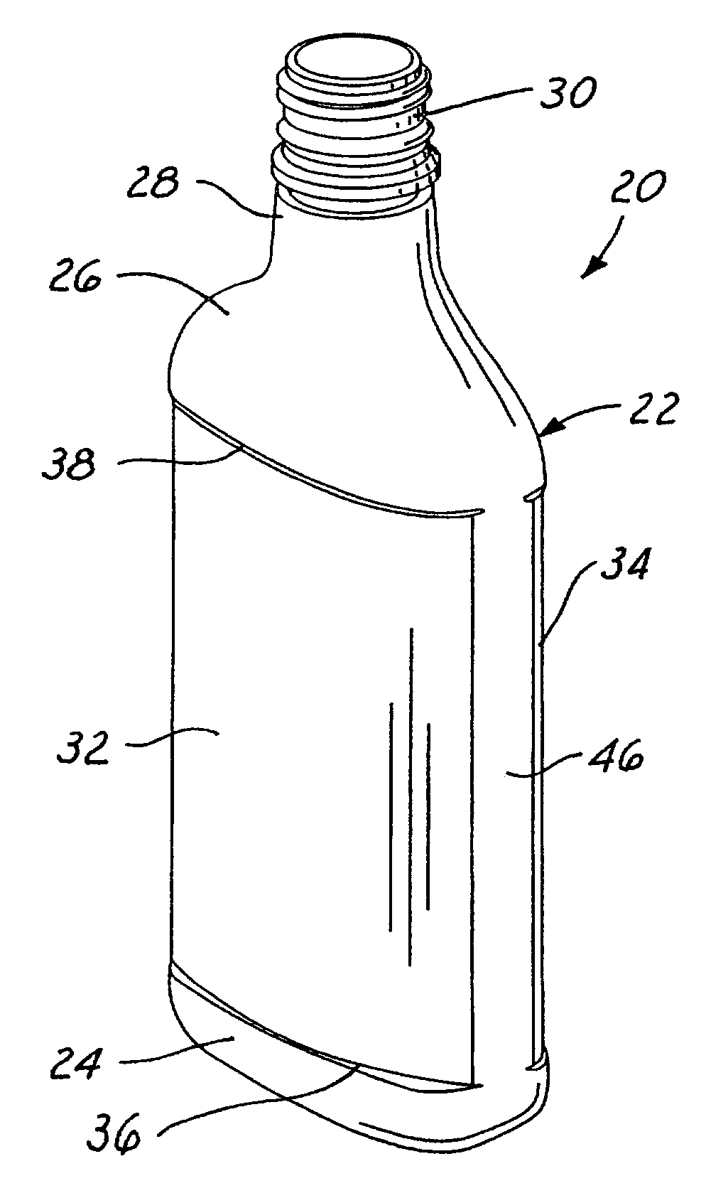
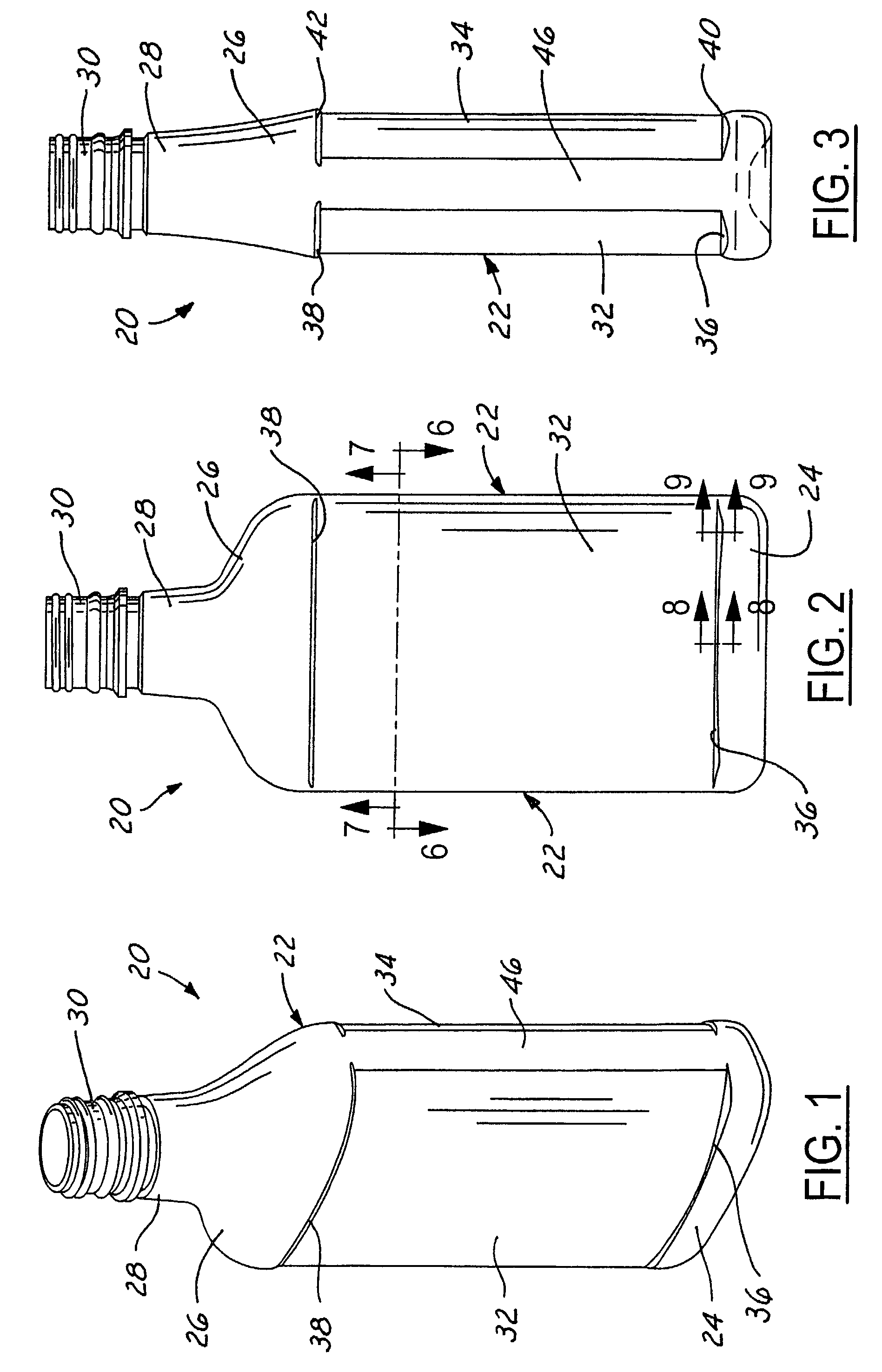
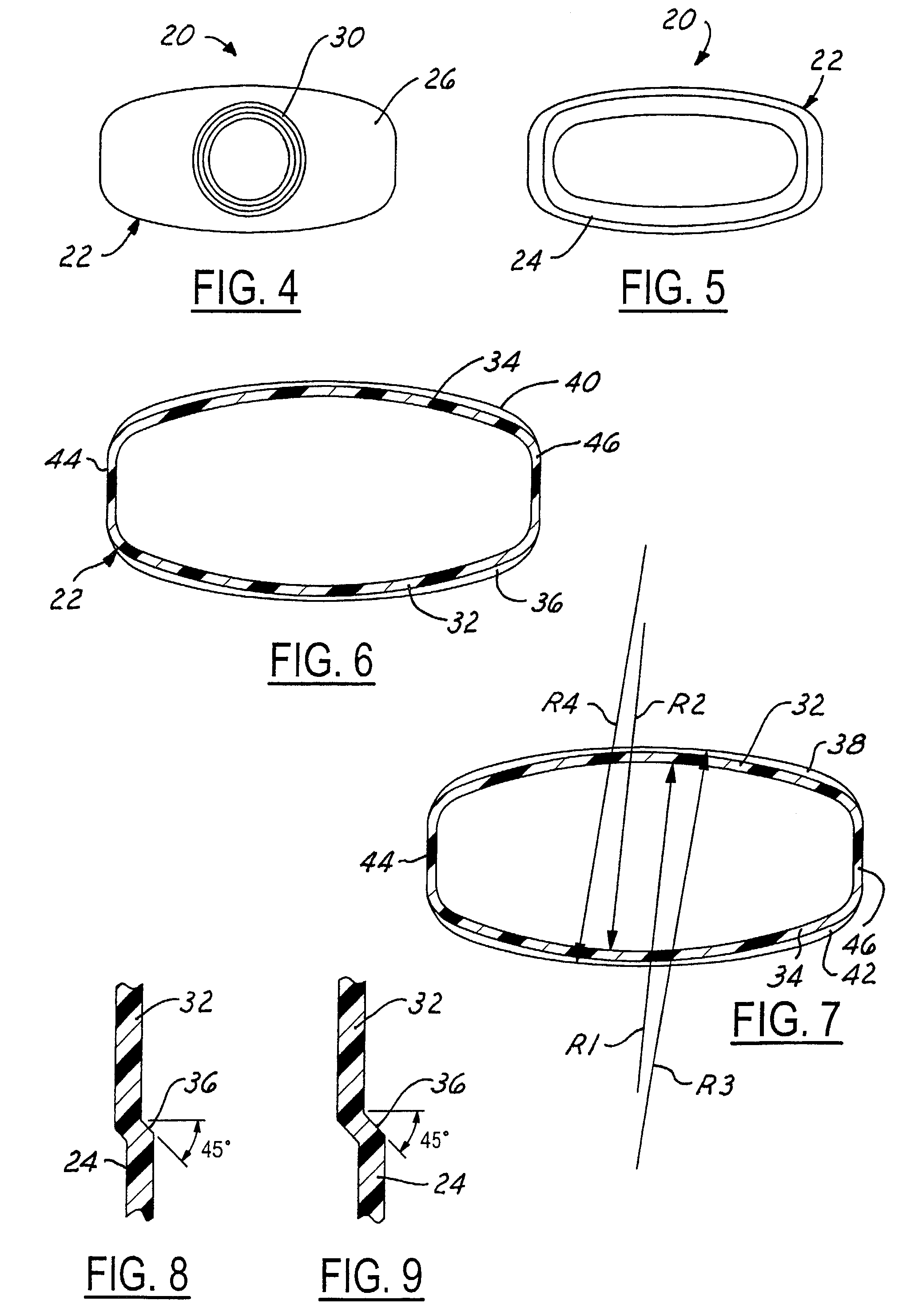
[0013]The drawings illustrate a dual convex flask 20 in accordance with one presently preferred embodiment of the invention as including a body 22 having a base 24 and a shoulder 26 that narrows into a neck 28 and an externally threaded finish 30. The contours of base 24, shoulder 26, neck 28 and finish 30 are exemplary only. Container body 22 has opposed convex front and back walls in the form of front and back label panel areas 32, 34. A pair of bumpers 36,38 are provided at the respective upper and lower ends of front label panel area 32. Likewise, a pair of bumpers 40, 42 are provided at the respective upper and lower ends of back label panel area 34. Upper bumpers 38, 42 are in the form of substantially axially downwardly facing shoulders or ledges between the lower ends of shoulder 26 and the upper ends of the label panel areas. Likewise, lower bumpers 36, 40 are in the form of substantially axially upwardly facing shoulders or ledges between the upper ends of container base 2...


PUM


Abstract

A dual convex flask is of one-piece integrally molded plastic construction. The flask has opposed front and back walls each with a convex label panel area at a first radius of curvature and axially spaced bumpers that extend outwardly from opposite ends of the panel area. Opposed substantially flat sidewalls connect adjacent side edges of the front and back walls. The bumpers on each of the front and back walls have a second radius of curvature that is greater than the first radius of curvature, such that the bumpers have a radial depth perpendicular to the label panel area which is greatest at the ends of the bumpers adjacent to the sidewalls and least at the center of the panel area.

Description

[0001]The present invention is directed to molded plastic flasks and methods of manufacture that are particularly well suited for use in vacuum filling operations.BACKGROUND AND SUMMARY OF THE INVENTION[0002]Flask-shaped containers are conventionally employed in some liquid product applications, such as liquor. Such flask-shaped containers have opposed relatively closely spaced front and back walls, and opposed relatively widely spaced sidewalls that interconnect the side edges of the front and back walls. Vacuum assistance is conventionally employed to increase the filling speed of liquid into containers, including flasks. Such vacuum-assisted filling involves withdrawal of air from the container interior while simultaneously injecting liquid into the interior. Vacuum-assisted filling typically does not present a problem with flask-shaped containers of glass construction, for example, because the container walls are sufficiently rigid to withstand the internal vacuum forces during ...

Claims


Application Information

Patent Timeline
IPC IPC(8): B65D1/00B65D1/40
CPCB65D1/0223B65D2203/02
Inventor WURSTER, MICHAEL P.
Owner GRAHAM PACKAGING PET TECH
Why Eureka
Try Eureka