Roof contact method for stope filling

A technology for stopes and backfills, which is applied in fields such as backfills, mining equipment, and earth-moving drilling, etc., and can solve the threats to mine workers and goaf residents, the failure of support forces to meet the support requirements, damage and negative effects It can reduce the surface subsidence, not affect the recovery speed, and reduce the filling cost.

Active Publication Date: 2018-11-16
GUANGXI ZHONGJIN LINGNAN MINING CO LTD
View PDF11 Cites 9 Cited by
  • Summary
  • Abstract
  • Description
  • Claims
  • Application Information

AI Technical Summary

Problems solved by technology

Solid filling is mainly to transport the slag on the stope to the goaf of the mine that needs to be treated for filling through a conveyor belt. This method of transportation is more difficult, consumes a lot of manpower, is more dangerous, and the effect is not obvious; fluid filling is mainly It is to inject cement mortar into the mined-out area of ​​the mine, but the existing fluid filling technology has poor roof connection effect; the gas filling mainly relies on putting the air bag in the goaf of the mine, and filling the air bag with air. This method is simple to operate , The cost is low, but the supporting force produced does not meet the supporting requirements; artificial roofing is to artificially lower the top layer by using techniques such as underground blasting. This method will still cause the ground to collapse and cause huge damage to the ground buildings. Formation of waterlogged areas on farmland, etc., making it impossible to cultivate
[0004] Therefore, the mined-out areas of these mines have brought serious threats to the mine workers and the residents of the mined-out areas; at the same time, the serious conflicts between the factory and the site due to the mined-outs will lead to mass incidents, and the destructive effects and negative The impact is relatively large, seriously affecting the stability and harmony of a region, and the filling and treatment of the goaf in the mine has become an urgent problem to be solved

Method used


Image

  • Roof contact method for stope filling
  • Roof contact method for stope filling

Examples


Embodiment Construction

[0042] Below is that the present invention is described in further detail in conjunction with the embodiment of the present invention:

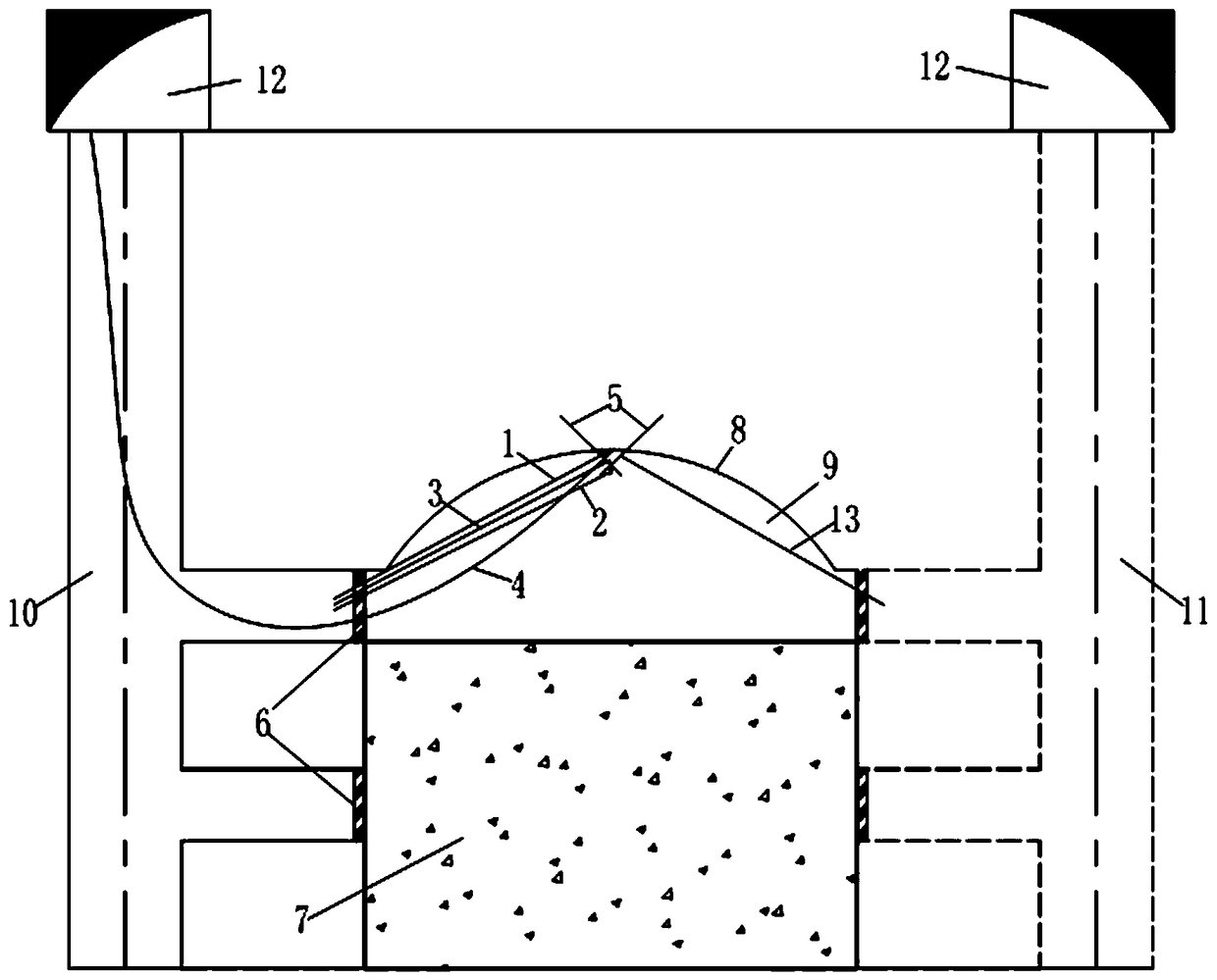
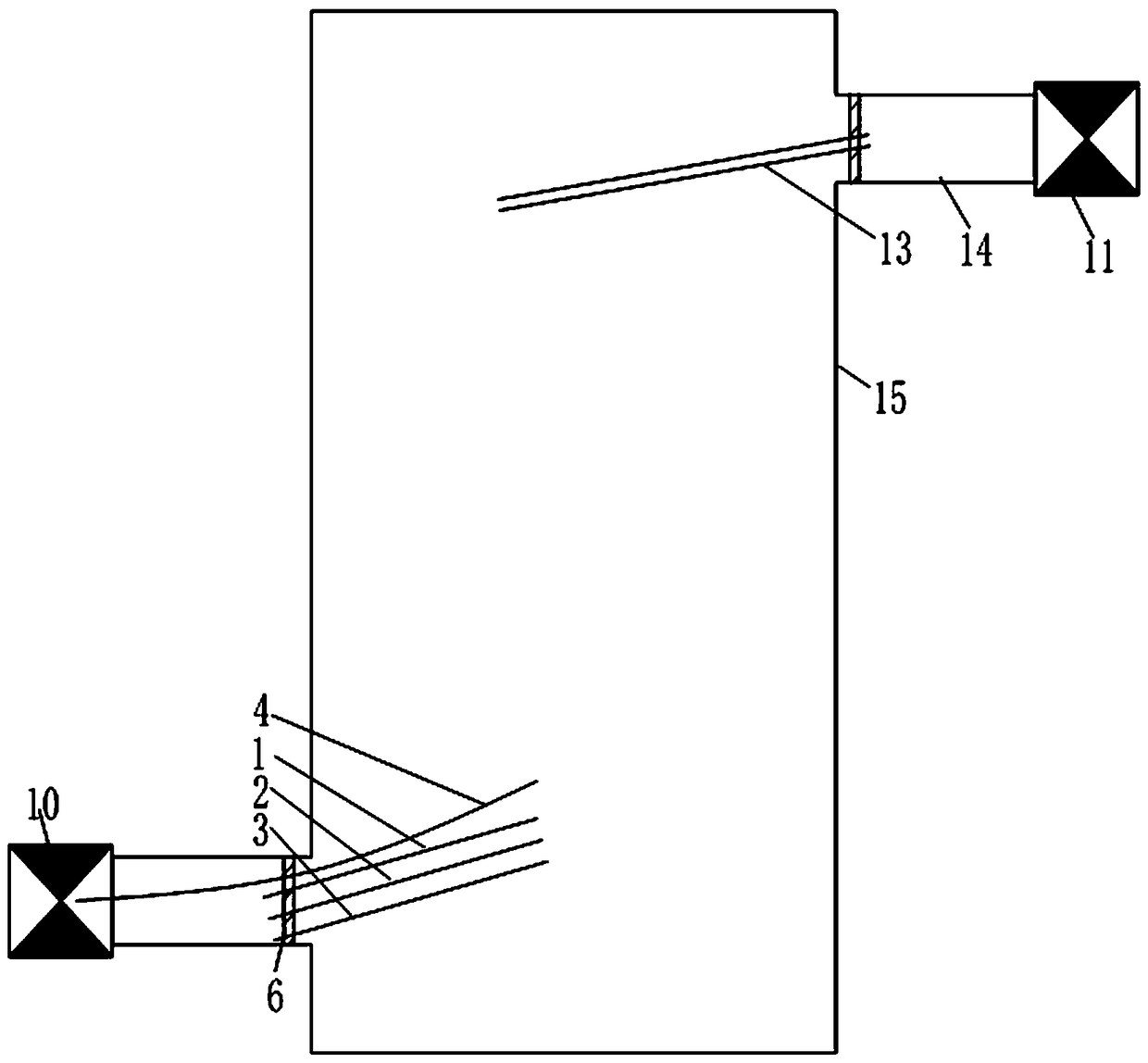
[0043] see Figures 1 to 2 Shown, a kind of top connection method of stope filling, described top connection method comprises the following steps:

[0044] (1) Effectively measure the roof and sides of the stope goaf;

[0045] (2) Use slag to fill normally to the predetermined position above the stope approach or contact road to obtain the filling body, and the remaining empty space is formed between the top surface of the filling body and the top of the stope empty area;

[0046] (3) Measure the height of the above remaining empty area to determine the highest point of the remaining empty area;

[0047] (4) Set the anchor rod at the highest point of the remaining empty space above, and install the outlet end of the filling pipe on the anchor rod;

[0048] (5) Separately install the first dehydration pipe to the highest point of the remain...


PUM


Abstract

The invention relates to the technical field of combustion water heaters, and relates to a roof contact method for stope filling. The roof contact method for the stope filling comprises the followingstep that a stope empty area is filled with slag to a certain height to obtain a residual empty area, the height of the residual empty area is measured, the position of the highest point is determined, a hollow anchor rod is installed at the highest point, and a filling pipe is installed on the hollow anchor rod; a first dewatering pipe and a dewatering pipe are installed at the highest point, anda third dewatering pipe and a second dewatering pipe are installed from top to bottom according to the height difference; and the opening between the residual empty area and an inlet or a connectingchannel is blocked, and then filling slurry is conveyed into the filling pipe to realize roof-contacted filling of the residual empty area. The roof contact method for the stope filling has the characteristics of realizing effective roof-contacted filling of the stope empty area, and effectively ensuring the strength of the stope empty area.

Description

technical field [0001] The invention relates to the technical field of mining field filling, in particular to a roofing method for stope filling, which is suitable for filling goafs in gold mines, iron mines, copper mines, coal mines, lead-zinc mines and other mines. Background technique [0002] The mined-out area of ​​the mine is the empty area left below the surface after mining. If it is not filled and treated, it will cause ground subsidence and other hazards. The subsidence area will not only lead to the depletion of groundwater, destruction of cultivated land, and deterioration of the ecological environment, but also damage nearby houses. Damage, ground fissure deformation of roads, or major projects such as highways, railways, airports, and urban buildings increase construction difficulty and input costs due to the collapse of goafs. In addition, the cracks formed by the surface subsidence will provide sufficient oxygen for the underground natural coal seam, and then...

Claims


Application Information

Patent Timeline
Patent Type & Authority Applications(China)
IPC IPC(8): E21F15/00
CPCE21F15/00
Inventor 李小元刘太取许毓海刘益龙支伟唐运坚黄楚铭罗俊森韦永锋练昌伟
Owner GUANGXI ZHONGJIN LINGNAN MINING CO LTD
Why Eureka
Try Eureka