Three dimensional manufacturing apparatus and method for manufacturing three dimensional manufactured product

a manufacturing apparatus and three-dimensional technology, applied in the direction of manufacturing tools, manufacturing enclosures, additive manufacturing processes, etc., can solve the problems of reducing the manufacturing speed, requiring a large driving force for the moving apparatus of the manufacturing stage, and reducing the viscosity of the light curing resin, so as to suppress the solidification, reduce the viscosity of the light, and increase the speed

Inactive Publication Date: 2018-03-01
CANON KK
View PDF2 Cites 8 Cited by
  • Summary
  • Abstract
  • Description
  • Claims
  • Application Information

AI Technical Summary

Benefits of technology

[0012]In the light of the above described problems, an object of the present invention is to increase a speed at which an uncured light curing resin is filled into a space for a next layer in a three dimensional manufacturing that repeats light curing of a light curing resin and moving of a manufacturing stage. Further, an object of the present invention is to suppress solidification, sticking and reduction in viscosity of the light curing resin in a vicinity of a transmitting section for curing light (manufacturing light), for example, by using gas having a curing inhibiting property.

Problems solved by technology

One of the factors that reduce the manufacturing speed is the problem that sticking (or viscosity increase) of the light curing resin occurs to the container of a resin, for example, a site of the light transmitting member that transmits curing light depending on the manufacturing conditions.
Further, there is also the problem that the moving apparatus of the manufacturing stage requires a large driving force.
Further, another factor that reduces the manufacturing speed is the problem that the light curing resin is not supplied quickly to the space where the next manufactured layer is formed when the manufacturing stage is moved after manufacturing one layer, which also depends on the manufacturing conditions.
When the manufactured layer is made small or divided into small pieces like a lattice structure, for example, in order to decrease the sectional areas in the respective layers of the manufactured product, there arises the problem that the strength of the manufactured product decreases.
Initially, the structure like the lattice form may not always match the structure of a desired manufactured product which is desired to be manufactured, in some cases.
Further, when the material with low viscosity is used for the light curing resin, there is the possibility of occurrence of the problem that shrinkage at the time of solidification becomes large and deformation of the manufactured product occurs, and the problem that the degree of polymerization at the time of light curing does not increase to cause reduction in strength, and decrease heat resistance.
However, when secondary curing is performed by post cure, the problems such as dimensional change and deformation at the time of curing are likely to occur.
Dividing the manufactured product (solidified layer) into small pieces, and reducing the viscosity of the light curing resin, with the supply speed of the light curing resin taken into consideration, cannot be said as essential solutions, and have the problem of causing various other unfavorable side effects.
Even by the method that causes the curing inhibiting gas to permeate as in U. S. Pat. No. 9216546 described above, it is not so easy to shorten the time period in which the material is filled into the space for the next layer of the thickness of 25 to 35 μm, for example, with the resin with high viscosity, and in the manufactured product in the shape with a large irradiation (curing) area of one layer.

Method used


Image

  • Three dimensional manufacturing apparatus and method for manufacturing three dimensional manufactured product
  • Three dimensional manufacturing apparatus and method for manufacturing three dimensional manufactured product
  • Three dimensional manufacturing apparatus and method for manufacturing three dimensional manufactured product

Examples


embodiment 1

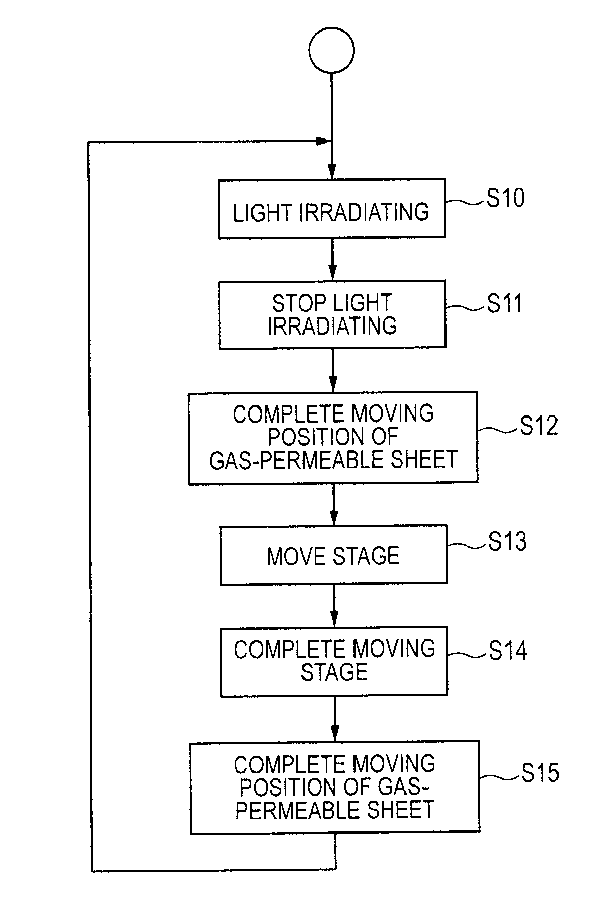
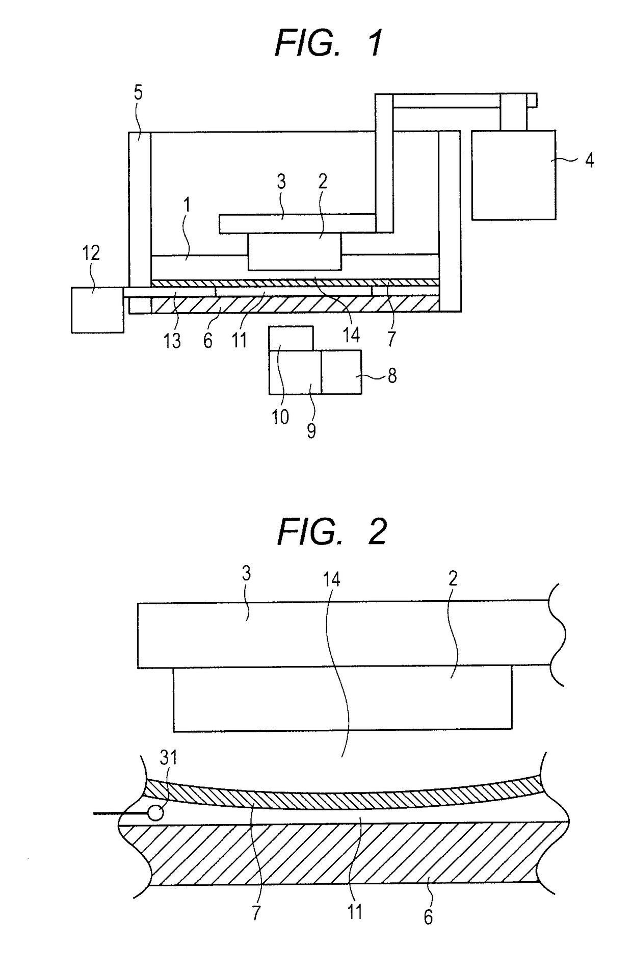
[0030]FIG. 1 illustrates a configuration of a three dimensional manufacturing apparatus for manufacturing a three dimensional manufactured product as a sectional structure, in embodiment 1. In FIG. 1, a light curing resin 1 in a molten (uncured) state is housed in a container 5. In the present description, a liquid light curing resin in a molten (uncured) state is described as a light curing resin.

[0031]As the light curing resin 1, a well-known light curing resin can be used. The light curing resin can include a monomer or an oligomer, a photopolymerization initiator, and various additives (a stabilizer, a filler, a pigment and the like). Further, both a monomer and an oligomer may be included. Monomers are organic materials that are polymerized into large molecules to form plastics. Oligomers are obtained by reacting some of monomers in advance and are materials that are polymerized into large molecules to form plastics similarly to monomers. A light polymerization initiator absorb...

embodiment 2

[0071]In embodiment 1, the configuration is illustrated, in which light irradiation for curing the light curing resin is performed from below the container 5, and the manufacturing stage 3 is moved upward by the lifting / lowering apparatus 4 for each layer formation as illustrated in FIG. 1, FIG. 2 and the like. However, the direction of light irradiation for curing the light curing resin 1, and the moving direction of the manufacturing stage 3 are not necessarily limited to the directions as described above.

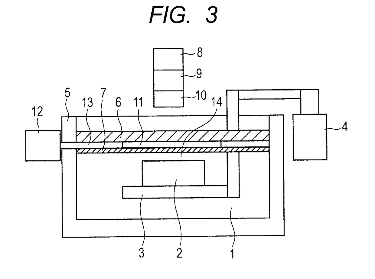
[0072]For example, as illustrated in FIG. 3, in a configuration in which light irradiation for curing the light curing resin 1 is performed from above the container 5, and the manufacturing stage 3 is moved downward by the lifting / lowering apparatus 4 for each layer formation, a configuration is conceivable, in which an equivalent operation and effect to the operation and effect of embodiment 1 are exhibited.

[0073]A manufacturing apparatus illustrated in FIG. 3 includes respectiv...

embodiment 3

[0078]FIG. 6 is a view schematically illustrating a section of the apparatus to describe a structure of a three-dimensional manufacturing apparatus according to embodiment 3 of the present invention.

[0079](Configuration of Apparatus)

[0080]In FIG. 6, reference sign 201 designates a container, reference sign 202 designates a light curing resin, reference sign 203 designates a resin supplying unit, reference sign 204 designates a light transmitting portion, reference sign 205 designates a light shielding portion, reference sign 206 designates a hydrophilic surface portion, reference sign 207 designates a light source, reference sign 208 designates a mirror unit, reference sign 209 designates a lens unit, reference sign 210 designates a light source unit, reference sign 211 designates a base, reference sign 212 designates a lifting / lowering arm, reference sign 213 designates a lifting / lowering unit, and reference sign 214 designates a three dimensional manufactured product.

[0081]The con...


PUM

PropertyMeasurementUnit
droplet diameteraaaaaaaaaa
droplet heightaaaaaaaaaa
thicknessaaaaaaaaaa

Abstract

A three dimensional manufactured product is manufactured A speed of filing an uncured light curing resin in a space for a next layer is enhanced, to improve a manufacturing speed. One surface of a container housing a light curing resin is configured by a gas-permeable sheet that faces the light curing resin, and transmits irradiation light of a light irradiating apparatus, and a light transmitting plate disposed at an outer side of the container from the gas permeable member. A pressurizing chamber controllable in pressure by a pressure controlling apparatus is defined between the gas-permeable sheet and the light transmitting plate. At moving a manufacturing stage, an inside of the pressurizing chamber is de-pressurized to cause the gas-permeable sheet to perform concave surface deformation, and at a time of performing light irradiation, gas in the pressurizing chamber is caused to permeate into the light curing resin by pressurizing.

Description

BACKGROUND OF THE INVENTIONField of the Invention[0001]The present invention relates to a three dimensional manufacturing apparatus that performs light irradiation to a light curing resin housed in a container and manufactures a three dimensional manufactured product and a method for manufacturing a three dimensional manufactured product.Description of the Related Art[0002]In recent years, the three dimensional manufacturing technology has been developed, which forms a manufactured product by repeating the process steps of exposing a light curing resin in an uncured state and solidifying (curing) the light curing resin. In the three dimensional manufacturing apparatus of this type, there is known a configuration in which the light curing resin as a material is applied in a layer by layer manner onto a manufacturing stage or a solidified manufactured product (work) with a coating roller or the like, and light irradiation is repeated. Further, there is also known a configuration in wh...

Claims


Application Information

Patent Timeline
Patent Type & Authority Applications(United States)
IPC IPC(8): B29C64/264B29C64/364B29C64/255C08F220/18B33Y10/00B33Y30/00
CPCB29C64/264B29C64/364B33Y30/00C08F220/18B33Y10/00B29C64/255B33Y50/00B33Y50/02C09D4/00C08F220/00B29C64/124B29C64/188B29C64/371B33Y40/00
Inventor ARAI, TAKASHISEKINE, YASUHIROKASHIWAZAKI, AKIOITO, TOSHIKI
Owner CANON KK
Why Eureka
Try Eureka