Motor control circuit for paper shredders

a motor control circuit and paper shredder technology, applied in cocoa, climate sustainability, energy industry, etc., can solve the problems of increasing power consumption, increasing load, and increasing power consumption, so as to improve shredding efficiency, advance energy saving, and control power consumption.

Inactive Publication Date: 2006-02-14
NAKABAYASHI CORP +1
View PDF6 Cites 58 Cited by
  • Summary
  • Abstract
  • Description
  • Claims
  • Application Information

AI Technical Summary

Benefits of technology

[0009]The present invention is to solve a conventional problem as described above and to disclose a paper shredder capable to control power consumption and advance energy saving by means of realizing a torque characteristic of low torque at high speed or high torque at low speed keeping an output of a motor within a stea

Problems solved by technology

On the other hand, if the product of a shredding capacity and shredding speed becomes higher, a maximum power output required to a motor also becomes higher, which results in more power consumption.
If a shredding capacity is therefore enhanced, energy saving cannot be achieved.
Also, as a high capacity motor brings a problem of a machine being oversized and heavy, aforementioned examples try to shred appropriately with a relatively small motor.
Further, a conventional paper shredder suspends power supply owing to a function of a circuit breaker against high voltage current caused when power consumption of a motor leaps upward as overloaded.
However, a load fluctuates during a shredding operation and an instant overload is frequently produced because of folds and wrinkles of p

Method used


Image

  • Motor control circuit for paper shredders
  • Motor control circuit for paper shredders
  • Motor control circuit for paper shredders

Examples


Embodiment Construction

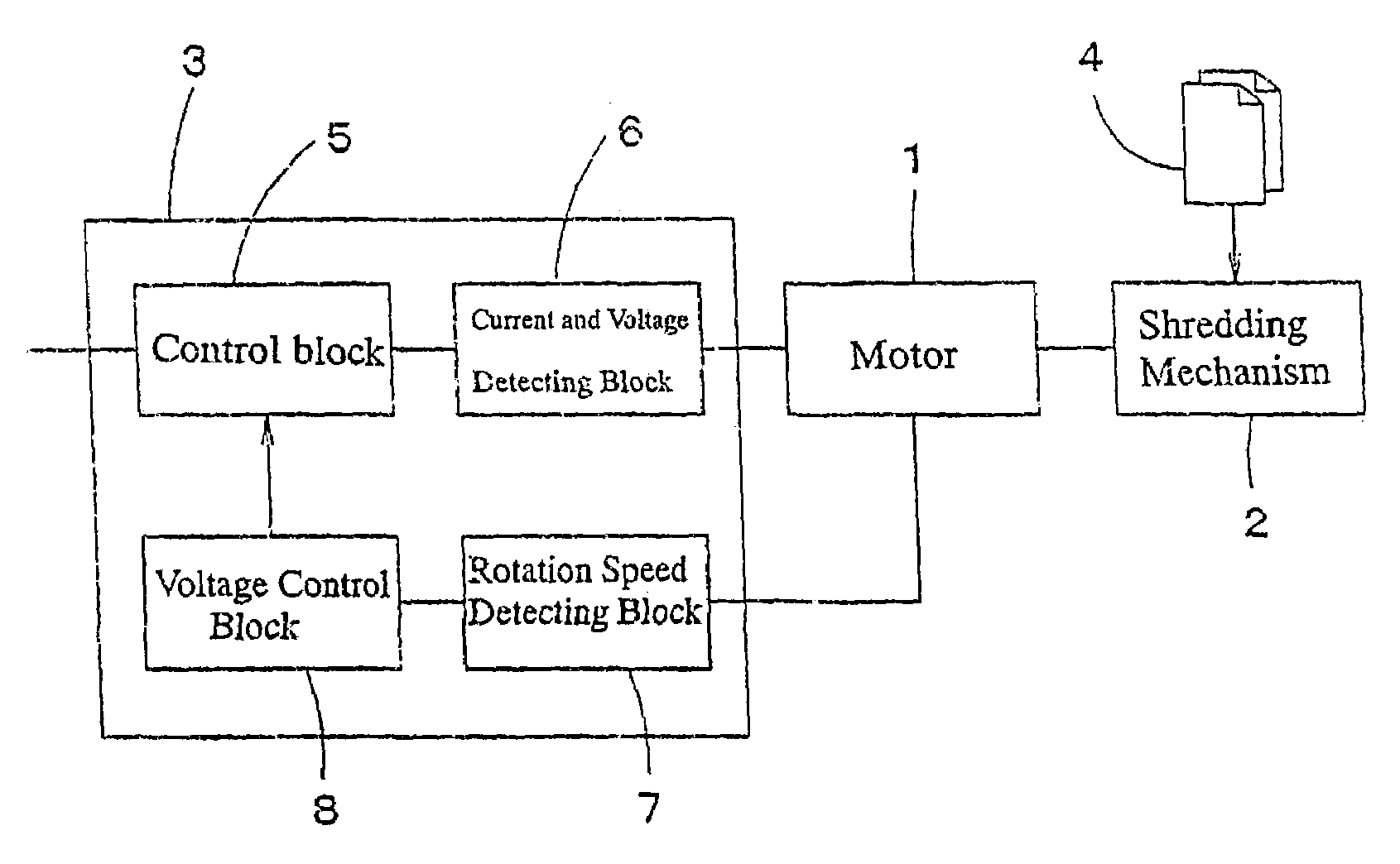
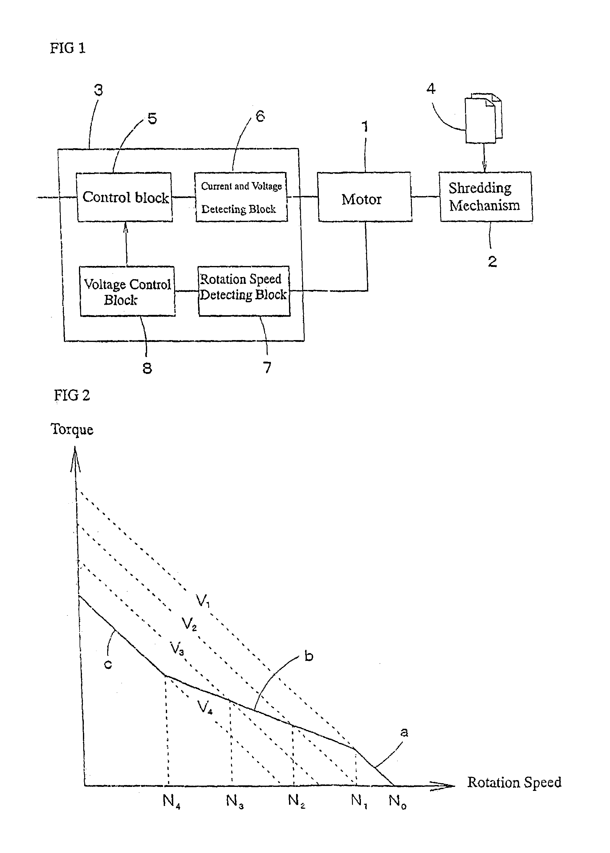
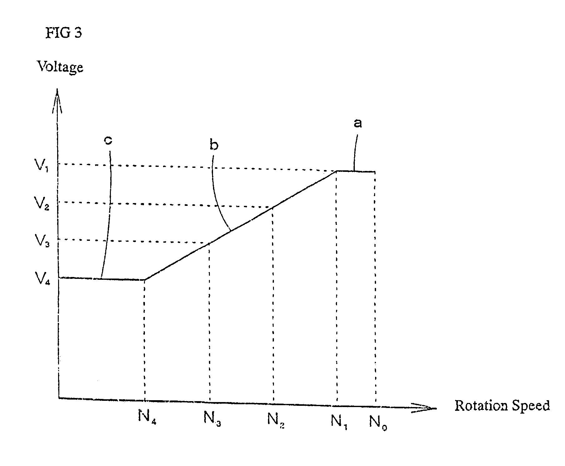
[0015]Hereinafter, preferred embodiments are discussed referring to attached drawings. FIG. 1 is one of preferable embodiments of a control circuit in the present invention. 1 is a motor for driving a rotary cutter in a paper shredder machine. In this embodiment, rotation speed and torque have an inversed linear correlation with each other if a voltage is a certain level. For example, a direct brushless motor can be adapted. 2 is a shredding mechanism having said rotary cutter therewithin, 3 is a control circuit for controlling On-Off or obverse-reverse rotation of said motor, and 4 is a paper to be shredded. A detailed block for said control circuit 3 is composed of a control block 5, a current and voltage detecting block 6, a rotation speed detecting block 7, and a voltage control block 8. In this block, said current and voltage detecting block constantly detects a current flow or a voltage for preventing said motor 1 from burned due to a sharp rise in a current which is caused wh...


PUM


Abstract

A paper shredder enables to control power consumption and achieve energy saving by realizing a torque characteristic of low torque at high speed or high torque at low speed keeping an output of a motor within a steady level. This circuit adopts a paper shredder structured with a driving motor for a rotary cutter having an inverted linear flow characteristic between rotation speed and torque and a control circuit composed of a detecting block for said rotation speed of said motor, a voltage control block for restricting a voltage output of said motor within a certain range in accordance with said rotation speed, and a current and voltage detecting block for monitoring a current flow of said motor. While a voltage is decreased on account of motor rotation speed which correlates negatively with a torque increase of said motor in shredding papers, when a voltage is restricted to a minimum by said voltage control block, an operation of said motor is to be suspended or reversed in the case that a current detected by said current and voltage detecting block exceeds a certain level. If a motor current detected by said current and voltage detecting block exceeds a certain level, a motor operation is to be suspended or reversed by a delaying circuit.

Description

BACKGROUND OF THE INVENTION[0001]1. Field of the Invention[0002]The present invention relates to a paper shredder for disposing papers with a rotary cutter driven by a motor and especially controls over the paper shredder capable to shred effectively by controlling motor torque in accordance with a supply of papers to be shredded.[0003]2. Description of the Related Art[0004]A paper shredder that shreds with high torque by controlling a rotary cutter to slow-speed rotation as overloaded and shreds speedy with low torque by controlling said rotary cutter to high-speed working as low loaded has been well known. The above technical idea enables to shred continuously without suspending a shredding operation, enhance operation efficiency and also solve troublesomeness in an operation control. Examples of such idea, that is Japanese Open Gazette No. H5-92143, Japanese Open Gazette H5-92144 or Japanese Open Gazette No. 2000-237615 can be referred.SUMMARY OF THE INVENTION[0005]Shredding capa...

Claims


Application Information

Patent Timeline
IPC IPC(8): B02C25/00B02C18/06B02C18/00B02C18/24H02P29/00
CPCB02C18/0007H02P29/02B02C2018/0038Y02P80/10
Inventor WATANO, HIROAKIOMURA, HIROMICHI
Owner NAKABAYASHI CORP
Why Eureka
Try Eureka