
Cylinder head gasket

a gasket and cylinder head technology, applied in the direction of engine seals, rain/draught deflectors, construction, etc., can solve the problems of difficult to obtain an even surface pressure around the cylinder bore, limited use materials, and limited number of sealing methods, so as to achieve good sealing performance, high tightening pressure, and high creep relaxation resistance

Active Publication Date: 2006-02-14
ISHIKAWA GASKET CO LTD
View PDF18 Cites 1 Cited by
  • Summary
  • Abstract
  • Description
  • Claims
  • Application Information

AI Technical Summary

Benefits of technology

[0017]With this structure, the bead has the portion with a wave shape located between the cylinder bores, thereby increasing a length of the bead. When the gasket is tightened, the bead receives a surface pressure at an increased area. As a result, as compared with a conventional gasket without the wave shape portion, it is possible to reduce creep relaxation at the portion. Accordingly, it is possible to maintain high sealing performance between the cylinder bores where a temperature is high and it is difficult to seal, thereby improving sealing performance with the structure.
[0022]In the present invention, the bead has the wave shape portion located between the cylinder bores for receiving a surface pressure at an increased bead area. Accordingly, the bead can withstand high tightening pressure and has good sealing performance with high creep relaxation resistance. It is possible to effectively prevent gas leak between the cylinder bores of a recent engine with a small size and low rigidity.

Problems solved by technology

Since only one or two structural plates are used, usable materials are limited for reducing a weight of an engine.
A type and the number of sealing methods are limited, so that it is necessary to use a relatively simple sealing method.
Accordingly, it is difficult to obtain an even surface pressure around a cylinder bore upon sealing with the cylinder head gasket.
That is, because of a structural problem around a cylinder bore, when the gasket is tightened, it is difficult to generate an enough sealing surface pressure at a low rigid portion, thereby causing gas leak at the portion.
As a result, the cylinder head and the cylinder block are deformed, thereby increasing a chance in which gas leaks between the cylinder bores.
When a small amount of gas leaks and enters a water hole or oil hole, gas enters liquid such as water and oil, thereby causing a problem in circulating water and oil and cooling the engine.
Since this causes a problem for the engine, it is necessary to provide a counter measure therefor.
Accordingly, a sealing member of a gasket does not function properly, and it is difficult to obtain good bore sealing performance.
However, in such a single bead structure with the straight portion, it may not be an enough solution for an increased temperature of the cylinder bore and lower rigidity of a recent engine.
As a result, it is difficult to combine complex sealing members.
Even though it is possible, a number of production steps increases, thereby increasing production cost.

Method used


Image

  • Cylinder head gasket
  • Cylinder head gasket
  • Cylinder head gasket

Examples


first embodiment

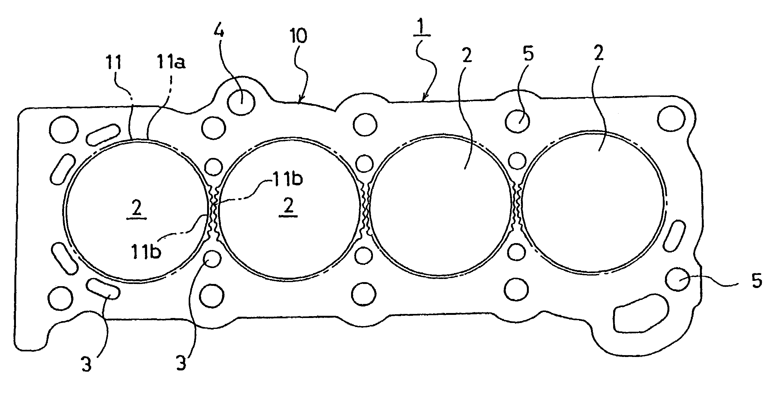
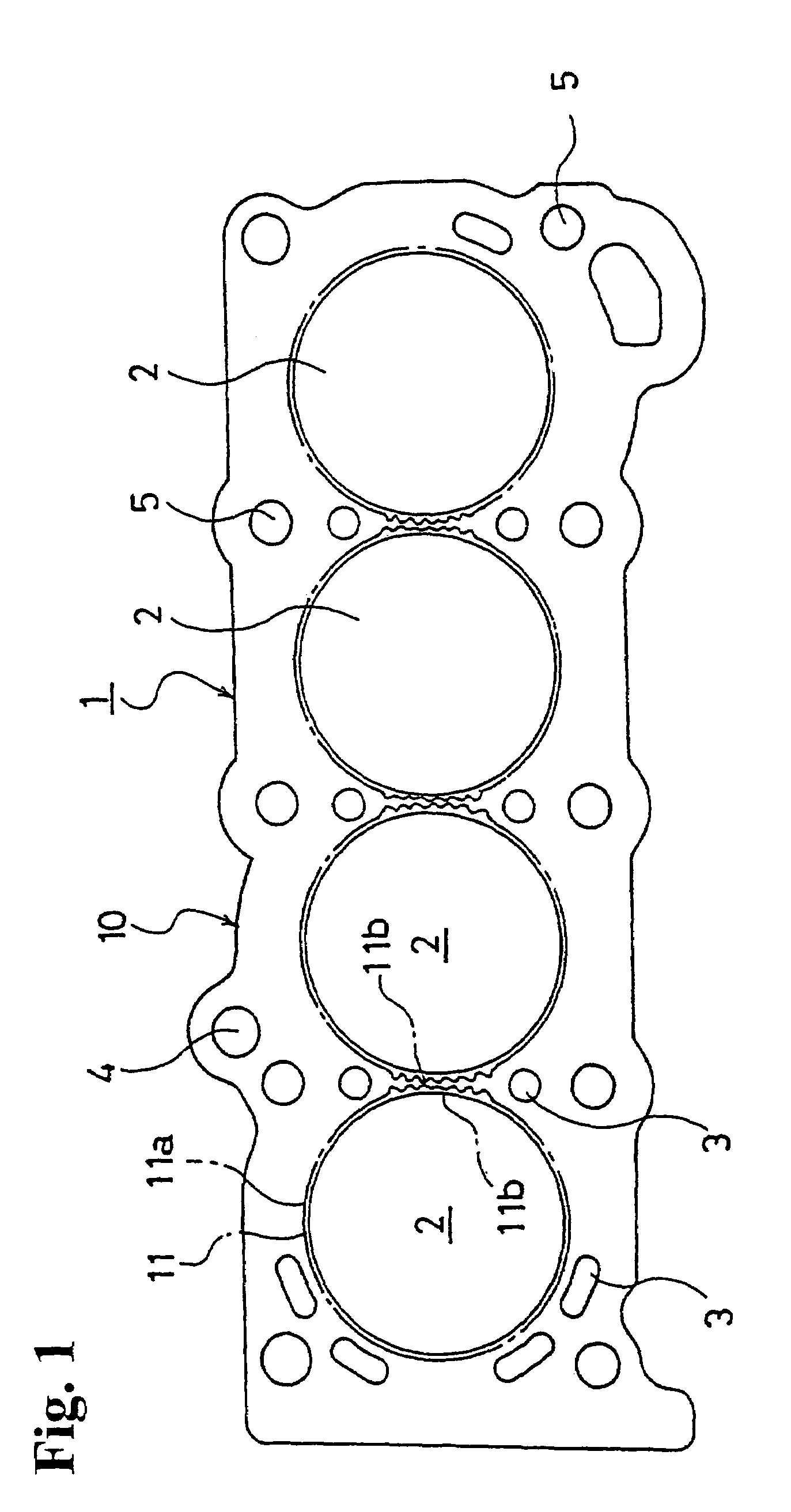
[0030] the cylinder gasket 1 shown in FIGS. 1 and 2 is formed of a single sheet of a metal plate 10. The metal plate 10 is made of annealed stainless steel (annealed material), or soft steel, and is formed in a shape corresponding to a shape of an engine part such as a cylinder block. The metal plate 10 is provided with cylinder bores 2, coolant water holes 3, oil holes 4 for circulating oil, and bolt holes 5 for tightening bolts. Beads 11 formed of full beads are arranged around the cylinder bores 2 as sealing means.

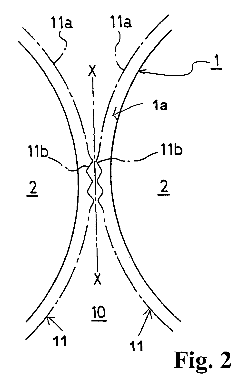
[0031]The beads 11 encircle the cylinder bores 2, respectively. In the first embodiment, as shown in FIGS. 1 and 2, the bead 11 has a portion 11a other than a portion 1a between the cylinder bores 2 formed in an arc shape along the cylinder bore 2 in a plan view. Only the portion located between the cylinder bores 2 is formed in a wave shape. Further, a wave shape portion 11b is arranged to face a wave shape portion of an adjacent bead 11. That is, the wave shape portio...

second embodiment

[0032]In a second embodiment, as shown in FIG. 3, beads 11A encircle the cylinder bores 2 formed in a metal plate 10A. The bead 11A has a portion 11Aa other than the portion between the cylinder bores 2 formed in an arc shape along the cylinder bore 2 in a plan view. Only the portion between the cylinder bores 2 is formed in a wave shape. Further, a wave shape of the wave shape portion 11Ab is arranged to enter a wave shape portion of an adjacent bead 11A. That is, the wave shape portions of the adjacent beads 11A are arranged generally parallel to each other.

[0033]With the structure of the cylinder head gasket 1A according to the second embodiment, it is possible to provide the wave shape portions 11Abof the beads 11A for the adjacent cylinder bores even when the portion between the cylinder bores 2 is small.

third embodiment

[0034]Further, in a third embodiment, as shown in FIG. 4, beads 11B encircle the cylinder bores 2 formed in a metal plate 10B. The bead 11B has a portion 11Ba other than the portion between the cylinder bores 2 formed in an arc shape along the cylinder bore 2 in a plan view. Only the portion between the cylinder bores 2 is formed in a wave shape. Further, a wave shape portion 11Bb is formed as a common wave shape portion 11Bb relative to the adjacent bead 11B. That is, the adjacent beads 11B cross and are connected at the portion between the cylinder bores 2 to form the common wave shape portion 11Bb.

[0035]The structure of the cylinder head gasket 1B according to the third embodiment is suitable for a case in which the portion between the cylinder bores 2 is extremely small.

[0036]The seal beads 11, 11A and 11B around the cylinder bores 2 are typically formed of a full bead with an arc shape, but not limited thereto. The beads may be formed of a full bead with a trapezoid shape and t...


PUM


Abstract

A cylinder head gasket is provided for dealing with gas leak between cylinder bores of an engine with a reduced size and rigidity. A cylinder head gasket is formed of a single metal plate provided with beads around cylinder bores. The bead has a portion formed in a wave shape only between adjacent cylinder bores. The wave shape portions may be arranged to enter with each other. The adjacent beads may be arranged such that the wave shape portions face each other. Alternatively, the adjacent beads may have a common wave shape portion.

Description

BACKGROUND OF THE INVENTION AND RELATED ART STATEMENT[0001]The present invention relates to a cylinder head gasket placed between two members such as a cylinder head and a cylinder block of an internal combustion engine.[0002]When joint surfaces between a cylinder head and a cylinder block (cylinder body) of an automobile engine are sealed, a metal cylinder head gasket is placed between the cylinder head and the cylinder block to seal combustion gas, coolant water, and lubrication oil.[0003]Such a cylinder head gasket has been changed from a laminated type having many layers of metal plates to a simple structure type composed of one or two metal plates for reducing a weight and production cost of an engine. Since only one or two structural plates are used, usable materials are limited for reducing a weight of an engine. A type and the number of sealing methods are limited, so that it is necessary to use a relatively simple sealing method.[0004]As a weight and size of an engine have ...

Claims


Application Information

Patent Timeline
Patent Type & Authority Patents(United States)
IPC IPC(8): F02F11/00F16J15/08
CPCF16J15/0818F16J2015/085E06B7/26E05Y2800/428
Inventor UDAGAWA, TSUNEKAZUKINOSHITA, YUUICHI
Owner ISHIKAWA GASKET CO LTD
Learn More