Reflecting mirror

a technology of reflecting mirror and mirror, which is applied in the field of reflecting mirror, can solve the problems of dirty surface of reflecting mirror and rain exposure of reflecting mirror, and achieve the effects of reducing the light transmittance of the transmittance changing part, and improving antidazzle

Active Publication Date: 2006-02-14
KK TOKAI RIKA DENKI SEISAKUSHO
View PDF7 Cites 13 Cited by
  • Summary
  • Abstract
  • Description
  • Claims
  • Application Information

AI Technical Summary

Benefits of technology

[0038]In a reflecting mirror of a fourth aspect of the invention, the thin film-shaped transmittance changing part in which the light transmittance changes under predetermined conditions is formed between the reflecting film and the substrate. Therefore, when the reflecting mirror of the invention is applied as a mirror for confirming a vehicle rear side, the ligh

Problems solved by technology

That is, since the reflecting mirror of this type is provided outside the vehicle, the reflecting mirror is exposed to rain in the rain.
On the other hand, in the reflecting mirror of this type, the component or the like (mainly organic substances) of the vehicle emission of other vehicles may adhere to the surface of the reflecting mirror in fine weather, and the surface thereof may be dirty.
A problem exists

Method used


Image

  • Reflecting mirror
  • Reflecting mirror
  • Reflecting mirror

Examples


first embodiment

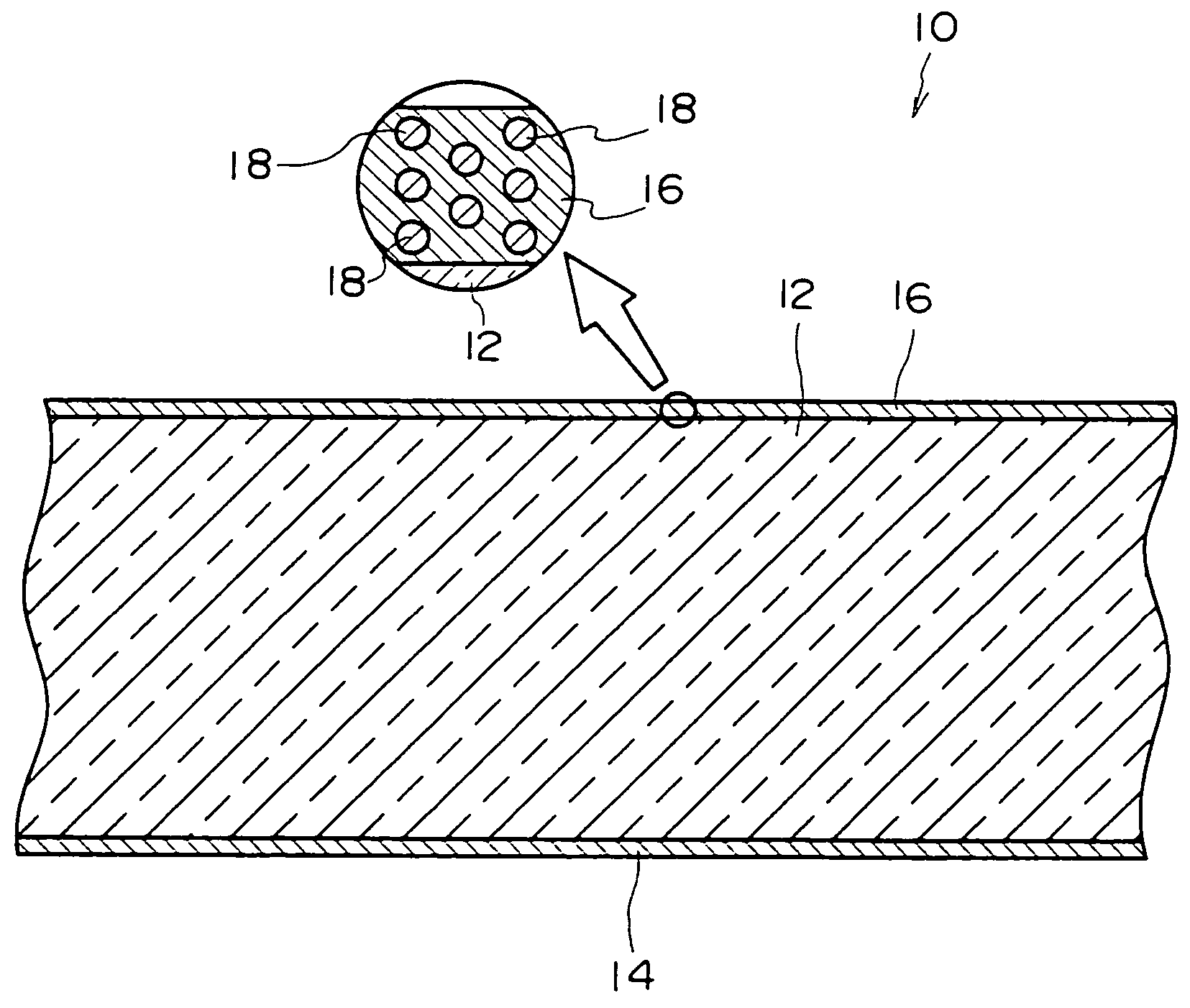
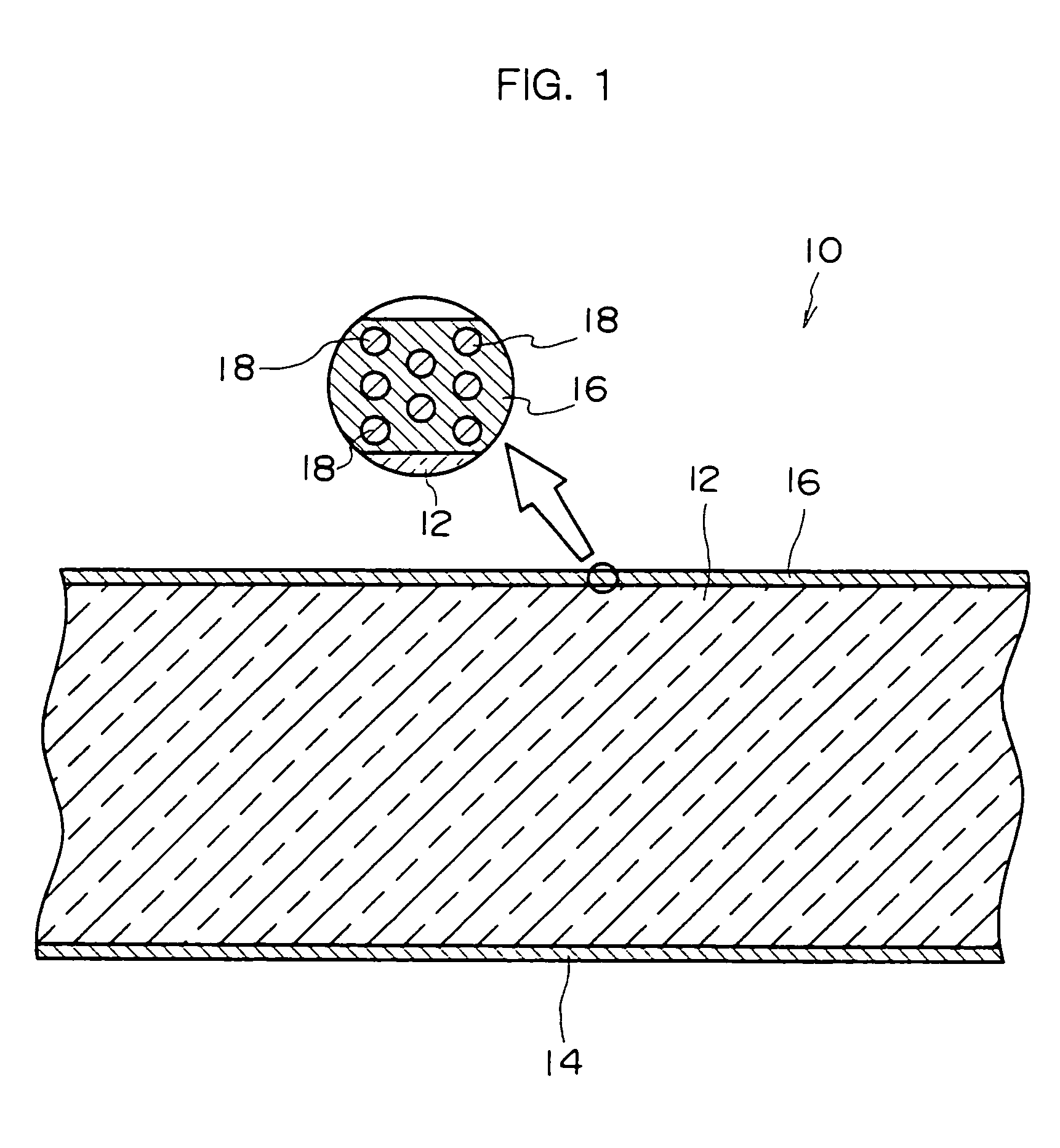
[0054]FIG. 1 shows a schematic cross-sectional view of a reflecting mirror 10 of the present invention.

[0055]As shown in FIG. 1, the reflecting mirror 10 comprises a glass substrate 12 as a substrate. A reflecting film 14 is formed on the back surface of the glass substrate 12.

[0056]For example, the reflecting film 14 is made of chrome or an alloy essentially consisting of the chrome. At least the surface of the side of the glass substrate 12 of the reflecting film 14 formed on the glass substrate 12 has sufficient luster, and high reflectivity. Therefore, when light entering from the surface side of the glass substrate 12 transmits in the glass substrate 12 and reaches the back surface of the glass substrate 12, the light is reflected by the reflecting film 14. The light reflected transmits in the glass substrate 12 again, and moves toward the surface side of the glass substrate 12.

[0057]In the embodiment, the reflecting film 14 is made of chrome or an alloy essentially consisting ...

second embodiment

[0078]FIG. 4 is a cross-sectional view showing a schematic structure of a reflecting mirror 30 of the invention.

[0079]As shown in FIG. 4, the reflecting mirror 30 comprises a conductive reflecting film 32 as a reflecting film in place of the reflecting film 14. The conductive reflecting film 32 is made of aluminum or an alloy essentially consisting of the aluminum. The surface of the side of the glass substrate 12 of the conductive reflecting film 32 has sufficient luster and high light reflectivity as well as the reflecting film 14 of the first embodiment.

[0080]An electrochromic film 34 which is a whole solid thin film as a transmittance changing part is formed on the back surface of the glass substrate 12 of the reflecting mirror 30 (the opposite side to the photocatalytic hydrophilic film 16).

[0081]The electrochromic film 34 comprises a transparent electrode film 36. The transparent electrode film 36 is made of an oxide of an alloy of indium and tin, so-called “ITO”. Also, the tr...

third embodiment

[0094]Next, the invention will be described.

[0095]FIG. 5 shows a schematic cross-sectional view of a reflecting mirror 60 of the third embodiment of the invention.

[0096]As shown in FIG. 5, in the reflecting mirror 60, an electrochromic layer 62 as a transmittance changing part is formed between the reflecting film 14 and the glass substrate 12.

[0097]The electrochromic layer 62 comprises a transparent glass substrate 64. A pair of transparent electrode films 36 are formed on the surface of the glass substrate 64 so as to oppose each other in the thickness direction of the glass substrate 64 (the surface of the side of the glass substrate 12).

[0098]The transparent electrode films 36 are connected to the power supply 40 through the switch 38, and voltage can be applied from the side of one transparent electrode film 36 or the side of the other transparent electrode film 36 by operating the switch 38 appropriately.

[0099]For example, a seal 66 is formed between one transparent electrode ...


PUM

PropertyMeasurementUnit
Fractionaaaaaaaaaa
Fractionaaaaaaaaaa
Thicknessaaaaaaaaaa

Abstract

In the reflecting mirror of the present invention, the film thickness of a photocatalytic hydrophilic film mainly made of silicon dioxide is set to about 90 nm, and the mass ratio of photocatalyst particles made of titanium dioxide contained in the photocatalytic hydrophilic film is set to about 60%. As a result, the hydrophilicity and the photocatalytic property can be sufficiently assured, and the surface reflectivity of the photocatalytic hydrophilic film can be effectively restrained. Therefore, the occurrence of a double image caused by the surface reflection of the photocatalytic hydrophilic film can be effectively restrained or be prevented.

Description

CROSS-REFERENCE TO RELATED APPLICATION[0001]This application claims priority under 35 USC 119 from Japanese Patent Application No. 2003-100273, the disclosure of which is incorporated by reference herein.BACKGROUND OF THE INVENTION[0002]1. Field of the Invention[0003]The present invention relates to a reflecting mirror which reflects light, and more preferably, relates to a reflecting mirror which is suitable as a door mirror and a fender mirror or the like provided outside of a vehicle.[0004]2. Description of the Related Art[0005]A reflecting mirror being referred to as a so-called door mirror for confirming rearward right and left (may be referred to as an outer view mirror) is provided to a vehicle. In the reflecting mirror, recently, a photocatalytic hydrophilic film consisting of a layer made of silicon dioxide (SiO2) and a layer made of titanium dioxide (TiO2) is formed on a glass substrate (see Japanese Patent Application Laid-Open (JP-A) No. 2000-239047 as one example of the...

Claims


Application Information

Patent Timeline
IPC IPC(8): G02B5/08B01J21/08B01J23/14B01J35/02B60R1/06B60R1/08G02F1/15G02F1/153
CPCB60R1/088G02F1/1533G02B5/08G02F2203/02
Inventor NAKAHO, JUNICHI
Owner KK TOKAI RIKA DENKI SEISAKUSHO
Why Eureka
Try Eureka