Motor rotor and manufacturing method thereof

Active Publication Date: 2006-02-14
DELTA ELECTRONICS INC
View PDF13 Cites 5 Cited by
  • Summary
  • Abstract
  • Description
  • Claims
  • Application Information

AI Technical Summary

Benefits of technology

[0013]In the method of manufacturing a motor rotor of the invention, since the outer surface of the rubber magnet is formed with patterns, the bending moment required can be reduced and the flexibility of the rubber magnet can be significantly improved.
[0014]Furthermore, an adhesive layer may be provided between the rubber magnet and the magnetic yoke. Since the outer surface of the rubber magnet is formed

Problems solved by technology

However, in the process mentioned above, the rubber magnet 100 is not so flexible that the two end surfaces of the rubber magnet 100 cannot be jointed perfectly after the rubber magnet 100 is bent.
When the above phenomenon takes place, the motor suffers from the non-u

Method used


Image

  • Motor rotor and manufacturing method thereof
  • Motor rotor and manufacturing method thereof
  • Motor rotor and manufacturing method thereof

Examples


Embodiment Construction

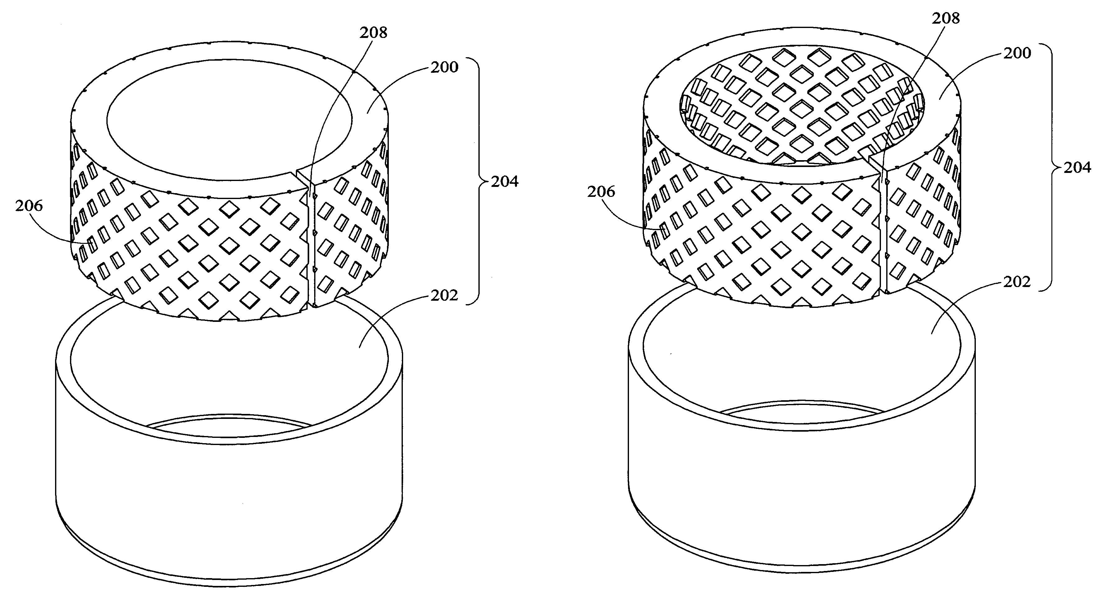
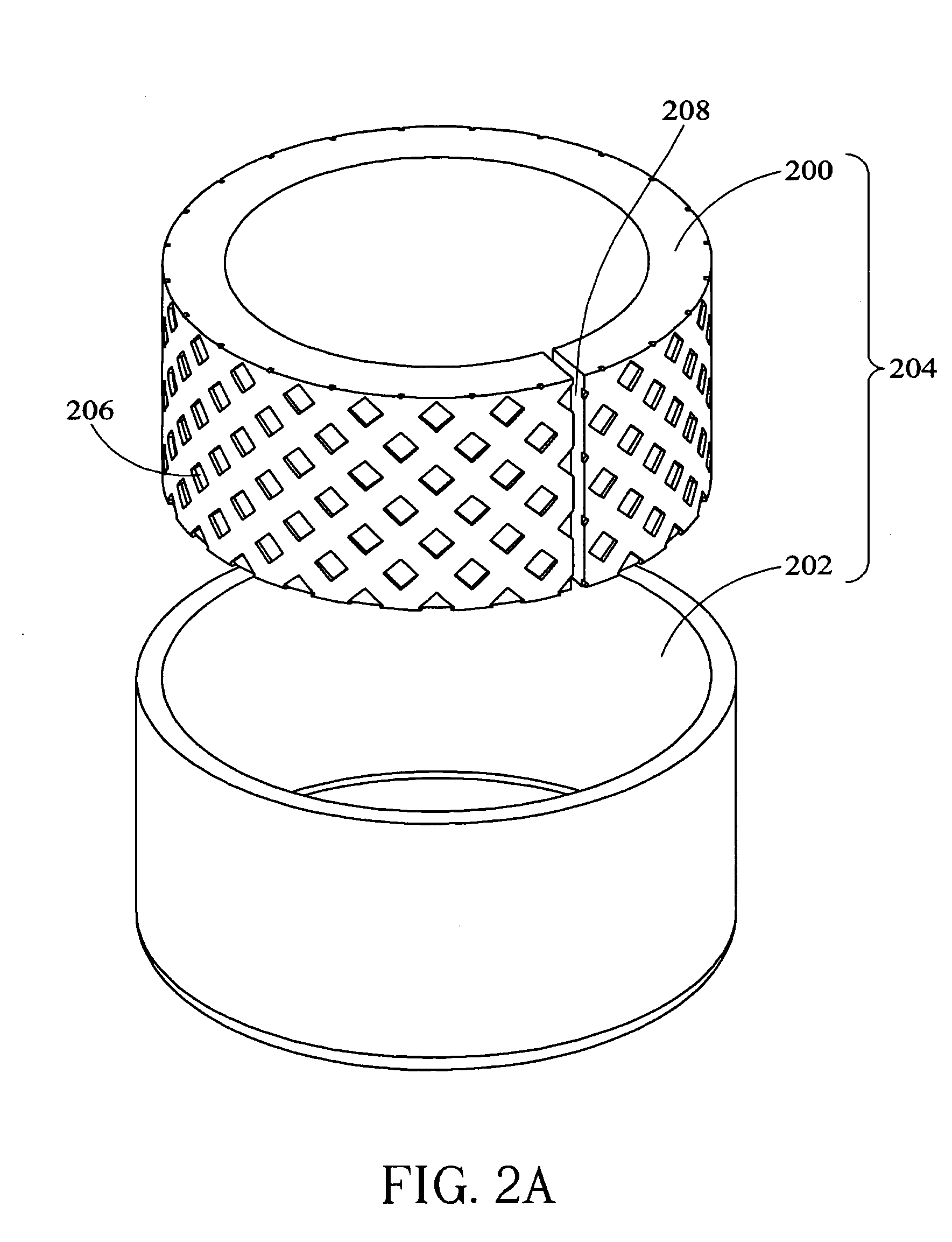
[0024]FIG. 2A is a schematic diagram showing the structure of the motor rotor according to an embodiment of the invention. As shown in FIG 2A, the motor rotor 204 includes a magnetic yoke 202 and a rubber magnet 200 provided inside the magnetic yoke 202. The magnetic yoke 202 with a shape, for example a ring shape, is made of conductive material such as metal. In the fabrication of the motor rotor 204, at first, a strip of the rubber magnet 200 made of magnetic rubber material with a smooth surface is selected. Then, one or more patterns 206 are formed on a first surface of the rubber magnet200 that faces the magnetic yoke 202. The first surface is the outer surface of the rubber magnet. The patterns 206 can be formed and distributed uniformly or fragmentarily on the whole surface or on portions of the surface. Moreover, the patterns 206 may be formed by various methods, such as press molding.

[0025]It should be noted that the patterns 206 may be embossing patterns 206a shown in FIG....


PUM

PropertyMeasurementUnit
Timeaaaaaaaaaa
Flexibilityaaaaaaaaaa
Adhesivityaaaaaaaaaa

Abstract

A motor rotor includes a magnetic yoke and a rubber magnet located within the magnetic yoke. At least one pattern is formed on a surface of the rubber magnet, which faces the magnetic yoke. The manufacturing method of the motor rotor is to provide a rubber magnet having flat surfaces, and at least one pattern is formed on a surface of the rubber magnet. The rubber magnet is curved to correspond with the inner surface of the magnetic yoke by the way that the patterned surface of the rubber magnet faces outside. The rubber magnet is put inside the magnetic yoke.

Description

BACKGROUND OF THE INVENTION[0001]1. Field of the Invention[0002]The invention relates to a motor rotor and its manufacturing method, and more particularly to a motor rotor having a rubber magnet with a pattern formed on the outer surface thereof for improving the flexibility of the rubber magnet of the motor rotor.[0003]2. Description of the Related Art[0004]A magnet is one of the essential components of a rotary machine, such as a motor. To reduce cost, cheap rubber magnets are used in conventional rotary machine structures.[0005]The schematic structure of a conventional motor rotor adopting rubber magnets is illustrated in FIG. 1. As shown in FIG. 1, the band-shaped rubber magnet 100 with a predetermined dimension is bent into a ring in the manufacturing process of a motor adopting a rubber magnet 100. Then, the ring-shaped rubber magnet 100 is pressed into a magnetic yoke 102 to complete the assembly of a motor rotor 104.[0006]However, in the process mentioned above, the rubber m...

Claims


Application Information

Patent Timeline
IPC IPC(8): H02K21/12H02K1/27H02K15/03
CPCH02K1/2786Y10T29/49009H02K1/2791
Inventor YEH, DUNG-CHANGLIN, YUNG-PING
Owner DELTA ELECTRONICS INC
Why Eureka
Try Eureka