Motor stop control device for gaming machine and gaming machine with the same

a technology of gaming machine and control device, which is applied in the direction of electric controller, dynamo-electric converter control, instruments, etc., can solve the problem of inefficiency of motor drive, and achieve the effect of efficient driving

Active Publication Date: 2006-02-14
UNIVERSAL ENTERTAINMENT CORP
View PDF14 Cites 58 Cited by
  • Summary
  • Abstract
  • Description
  • Claims
  • Application Information

AI Technical Summary

Benefits of technology

[0010]The present invention has been done in order to dissolve the above problems and has an object to provide a motor stop control device in which a motor can be efficiently driven and a constant voltage can be applied to the motor when the motor is stopped, thereby the reel can be stopped first, and to provide a gaming machine with the motor stop control device.
[0019]According to the above motor stop control device, it is executed a chopping control in which the voltage with on-time and off-time is repeatedly applied to the motor when the motor is started to rotate and is rotating at the constant speed and the stop control without the above chopping control is executed at the time that the motor is stopped. Accordingly, the motor stop control device can efficiently drive the motor when the motor is started to rotate and is rotating at the constant speed and the constant voltage can be applied to the motor when the motor is stopped, therefore the reel can be stopped first.
[0020]As mentioned in the above, the present invention can provide the motor stop control device and the gaming machine with the motor stop control device through which the motor can be efficiently driven and the constant voltage can be applied to the motor when the motor is stopped, therefore the reel can be stopped first.

Problems solved by technology

However, in the above circuitry construction, although a current flows in the motor by applying a predetermined voltage to the motor, the current has a characteristics of a first order lag against the voltage, therefore there is a problem that the motor cannot be efficiently driven.
This leads to stopping the reels first from the viewpoint of control circuit, since the reels cannot be physically stopped at the same time as the transmittance of the stop control signal.

Method used


Image

  • Motor stop control device for gaming machine and gaming machine with the same
  • Motor stop control device for gaming machine and gaming machine with the same
  • Motor stop control device for gaming machine and gaming machine with the same

Examples


Embodiment Construction

[0034](Basic Construction of Motor Drive Control Device)

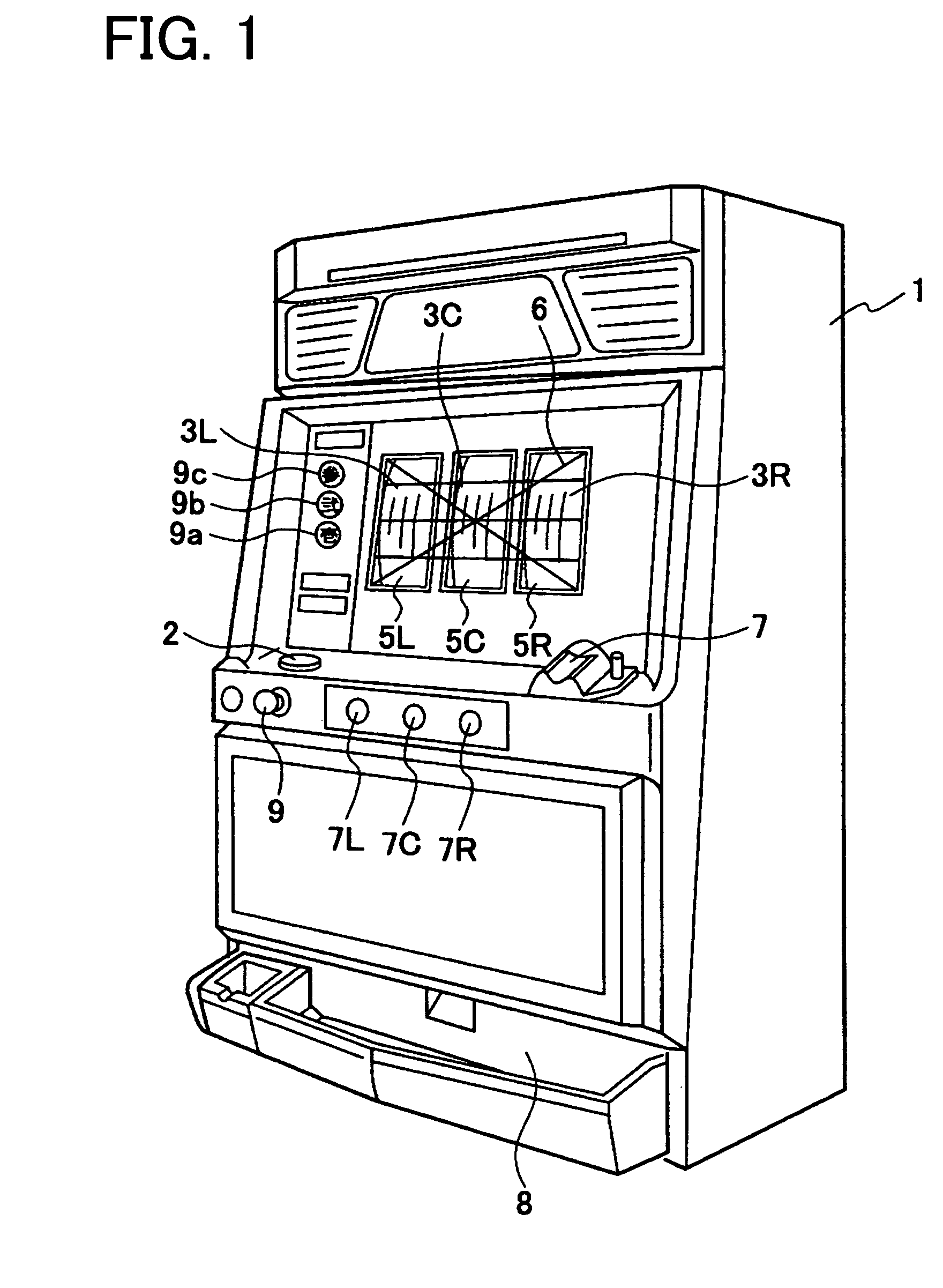
[0035]The motor stop control device of the embodiment will be described with reference to the drawings. FIG. 1 is a perspective view of a reel-type gaming machine according to the embodiment.

[0036]As shown in FIG. 1, in front of a cabinet forming a whole construction of the reel-type gaming machine 1, three panel display windows 5L, 5C, 5R are formed. Reels 3L, 3C, 3R constructing a reel unit are seen and recognized through the panel display windows 5L, 5C, 5R, respectively. And on the panel display windows 5L, 5C, 5R, three pay lines 6 are described along three horizontal directions and two pay lines 6 are described along two oblique directions. These pay lines 6 are made effective according to the number of coins inserted through an insertion slot 7 and the number of pay lines 6 are determined.

[0037]Each of the reels 3L, 3C, 3R starts to rotate when a player inserts coins in the insertion slot 7 and operates a start lever 9. ...


PUM


Abstract

In the gaming machine, when the motor drive instruction to drive the motor occurs based on an instruction from an external, a constant voltage is applied to the motor and the motor is driven through the motor drive circuit 39. And when the excitation current value flowing in the motor becomes the first current value based on the constant voltage applied to the motor through the motor drive circuit 39, the voltage with on-time and off time is repeatedly applied to the motor through the motor drive circuit 39. Further, when the rotation speed of the motor becomes constant based on the voltage with on-time and off-time applied through the motor drive circuit 39, the constant voltage is applied to the motor based on the motor stop instruction through the motor drive circuit 39, thereby the motor is stopped.

Description

CROSS-REFERENCE TO THE RELATED APPLICATION (S)[0001]This application is based upon and claims a priority from the prior Japanese Patent Application No. 2003-392452 filed on Nov. 21, 2003, the entire contents of which are incorporated herein by reference. This application is related to co-pending U.S. applications entitled “MOTOR STOP CONTROL DEVICE UTILIZABLE FOR REEL-TYPE GAMING MACHINE”, filed on Apr. 29, 2004, and “MOTOR STOP CONTROL DEVICE FOR GAMING MACHINE AND GAMING MACHINE PROVIDED WITH THE MOTOR STOP CONTROL DEVICE”, filed on Jul. 30, 2004 and “MOTOR DRIVE CONTROL DEVICE UTILIZABLE FOR REEL-TYPE GAMING MACHINE”, filed on Sep. 9, 2004 and “MOTOR STOP CONTROL DEVICE UTILIZABLE FOR GAMING MACHINE AND GAMING MACHINE USING THE SAME”, filed on Sep. 15, 2004, “MOTOR STOP CONTROL DEVICE UTILIZABLE FOR GAMING MACHINE AND GAMING MACHINE USING THE SAME”, filed on Sep. 30, 2004. The co-pending applications are expressly incorporated herein by reference.BACKGROUND OF THE INVENTION[0002]...

Claims


Application Information

Patent Timeline
Patent Type & Authority Patents(United States)
IPC IPC(8): H02P7/00A63F5/04G07F17/34H02P8/24
CPCG07F17/3202G07F17/34G07F17/3213
Inventor SUZUKI, YUUICHIROU
Owner UNIVERSAL ENTERTAINMENT CORP
Why Eureka
Try Eureka