Power supply for a pulsed load

a pulsed load and power supply technology, applied in the field of power supply, can solve the problems of large voltage drop, less able to supply peak current demand without the device cutting, and detrimental to the battery

Inactive Publication Date: 2006-02-14
CAP XX LTD
View PDF13 Cites 31 Cited by
  • Summary
  • Abstract
  • Description
  • Claims
  • Application Information

AI Technical Summary

Benefits of technology

[0027]a supercapacitor connected in parallel with the terminals for maintaining the ratio of the range of instantaneous power provided by the battery and the average value of the power provided by the battery at less than a predetermined threshold.
[0031]a supercapacitor connected in parallel with the terminals for maintaining the ratio of the range of instantaneous power provided by the battery and the average value of the power provided by the battery at less than a predetermined threshold.

Problems solved by technology

When the battery is nearly flat or is old, its' effective internal resistance tends to increase, and it is less able to supply peak current demand without the device cutting out.
Heavy load pulses generally also cause a large voltage drop when they occur, and this may be detrimental to the battery.
Lithium-ion batteries are particularly susceptible to damage in this way.
As a result, pulse loads invariably reduce battery run-time as the load will have a minimum threshold supply voltage required at all times. When the load pulses and that voltage drop below the minimum threshold, the electronic device must shut down as the voltage regulating circuitry is no longer able to supply the necessary voltage to run key circuits.
While this circuitry is designed to protect the battery, it also results in shut down of the device when the peak current, although being over the threshold, was so for only a short period.
For mobile telephone and personal computing applications this is a source of frustration to users.

Method used


Image

  • Power supply for a pulsed load
  • Power supply for a pulsed load
  • Power supply for a pulsed load

Examples


Embodiment Construction

[0057]The following terms are used in the specification in the following manner:[0058]1. “laptop computer” and “notebook computer” are used interchangeably and are intended to include portable computing devices, particularly those having on board rechargeable energy storage devices;

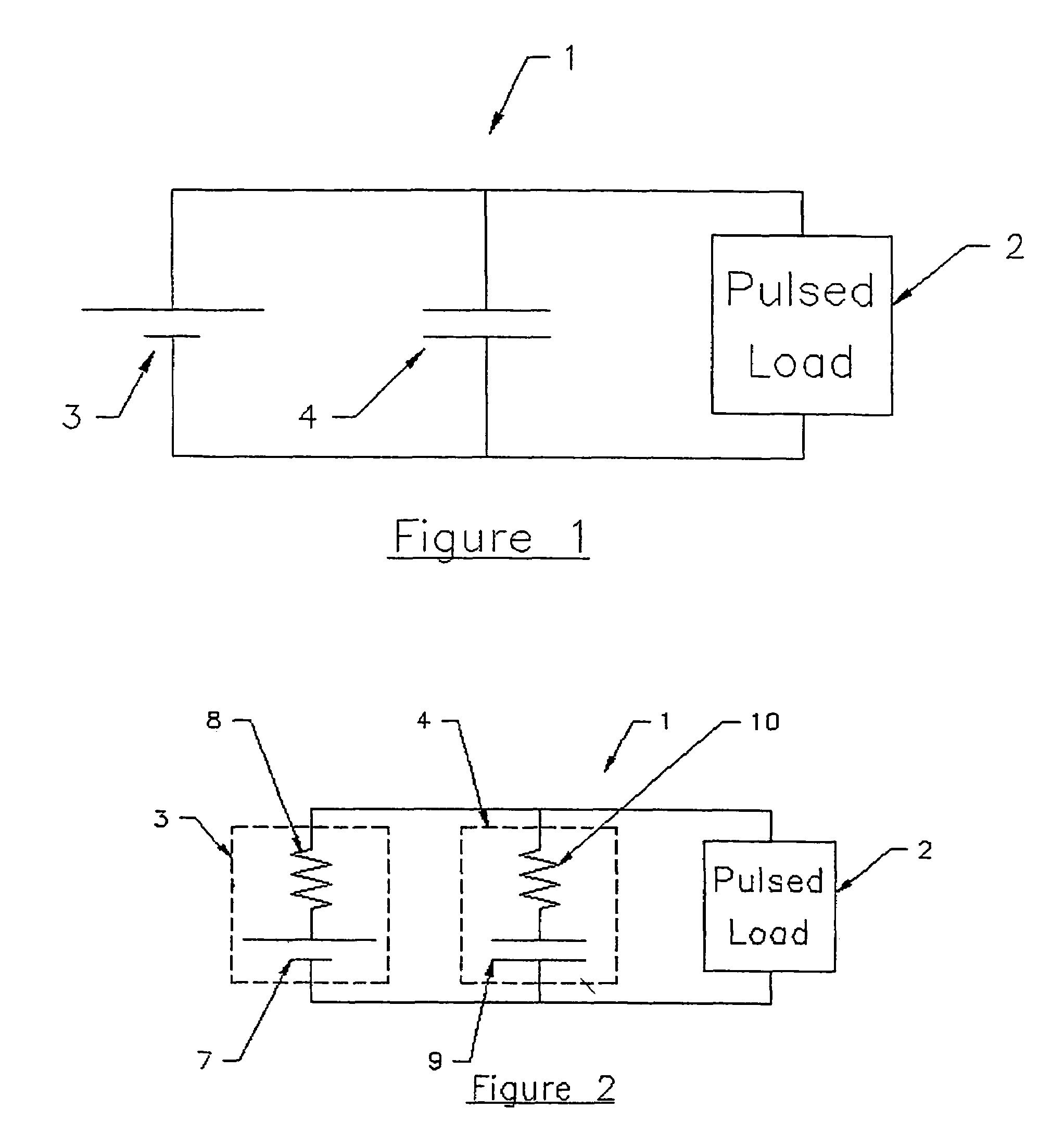
[0059]an ideal battery 7 in series with an internal resistance 8; and

[0060]an ideal capacitor 9 in series with an equivalent series resistance (ESR) 10.

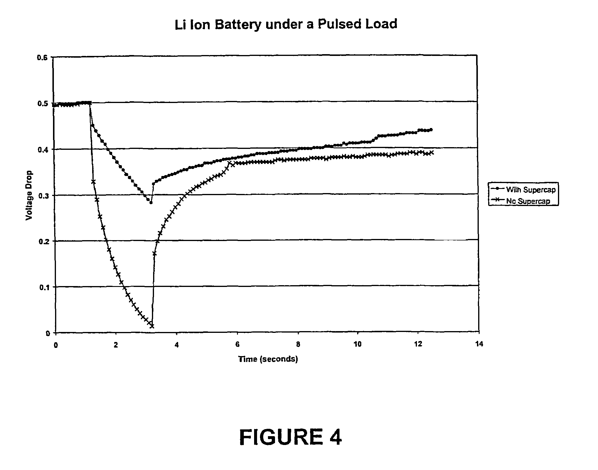
[0061]Through use of a supercapacitor 4 having a low ESR with respect to the resistance 8, the power supply 1 facilitates continuity of supply to load 2. That is, during peak demand more of the load current will be supplied by supercapacitor 4 due to the lower ESR. Moreover, during times of lower load current demands the battery recharges the supercapacitor. This reduces the peak current needed to be provided by the battery and thereby improves battery longevity.

[0062]That is, this parallel hybrid combination of a supercapacitor and a battery allows a redu...


PUM

PropertyMeasurementUnit
internal resistanceaaaaaaaaaa
capacitanceaaaaaaaaaa
temperaturesaaaaaaaaaa

Abstract

A power supply (1) for a pulsed load (2) includes a first energy storage device in the form of a battery (3) which is in parallel with a second energy storage device in the form of a supercapacitor (4). Battery (3) and supercapacitor (4) are respectively modelled as: an ideal battery (7) in series with an internal resistance (8); and an ideal capacitor (9) in series with an equivalent series resistance (ESR) (10). Through use of a supercapacitor (4) having a low ESR with respect to the resistance (8), the power supply (1) facilitates continuity of supply to load (2). That is, during peak demand more of the load current will be supplied by supercapacitor (4) due to the lower ESR. Moreover, during times of lower load current demands the battery recharges the supercapacitor. This reduces the peak current needed to be provided by the battery and thereby improves battery longevity.

Description

[0001]This is a continuation of application Ser. No. 10 / 276,408 filed 10 Apr. 2003, which is a 371 of PCT / AU01 / 00553 filed 15 May 2001, which claims priority to Australian Application No. PQ 7504 filed 15 May 2000 the contents of which are incorporated herein by reference in their entirety.FIELD OF THE INVENTION[0002]The present invention relates to a power supply.[0003]The invention has been developed primarily for use with mobile telephones and will be described hereinafter with reference to that application. It will be appreciated, however, that the invention is not limited to that particular field of use and is also suitable for other electronic devices, particularly portable devices such as Notebook computers, palmtop computers, electronic organisers, two-way pagers, remotely powered electronic device and the like.BACKGROUND OF THE INVENTION[0004]Pulsed loads occur in many battery-powered portable devices and the peak current may be many times the resting current. When the batt...

Claims


Application Information

Patent Timeline
Patent Type & Authority Patents(United States)
IPC IPC(8): H01M10/46G06G7/62H02J7/34
CPCH02J7/345
Inventor TURNER, GEOFFREY ALANPAUL, GEORGE LANGEKESHISHIAN, SARKISMAHON, PETER JOHN
Owner CAP XX LTD
Why Eureka
Try Eureka