
Method and apparatus for impedance matching in systems configured for multiple processors

a technology of impedance matching and processor, applied in the field of computer systems, can solve the problems of insufficient pin-to-pin electrical connections, inability to match the impedances of coupled signal lines, and inability to provide a connection between two buses across the processor slo

Inactive Publication Date: 2006-02-14
GLOBALFOUNDRIES INC
View PDF12 Cites 31 Cited by
  • Summary
  • Abstract
  • Description
  • Claims
  • Application Information

AI Technical Summary

Benefits of technology

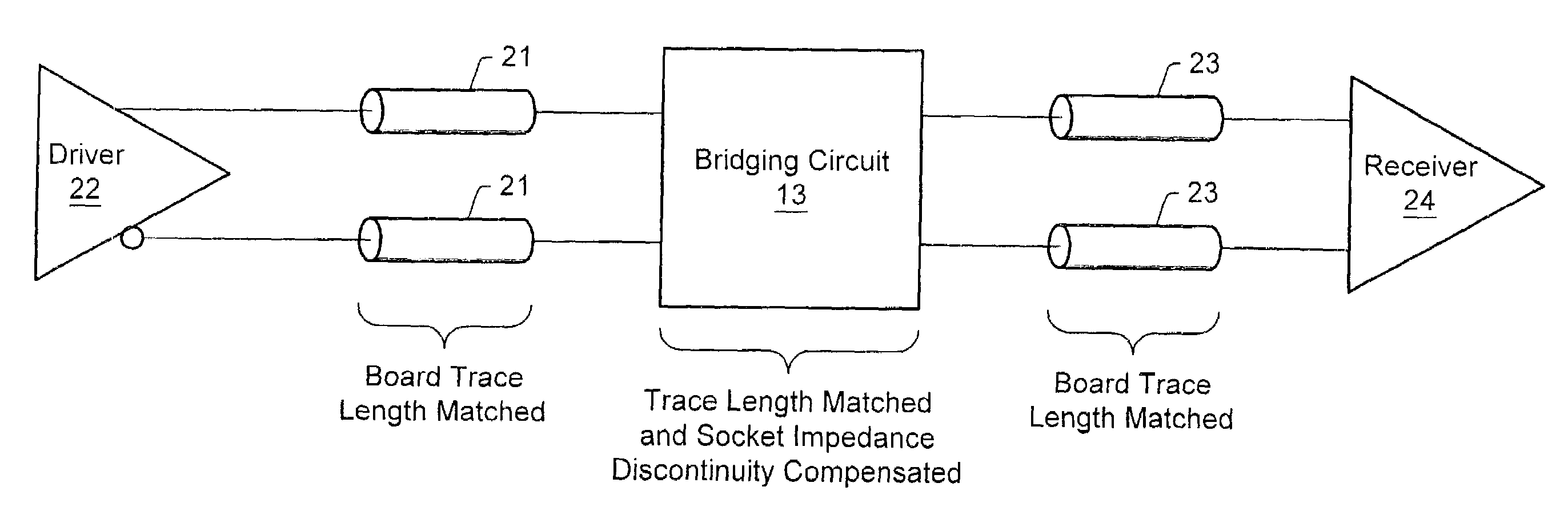
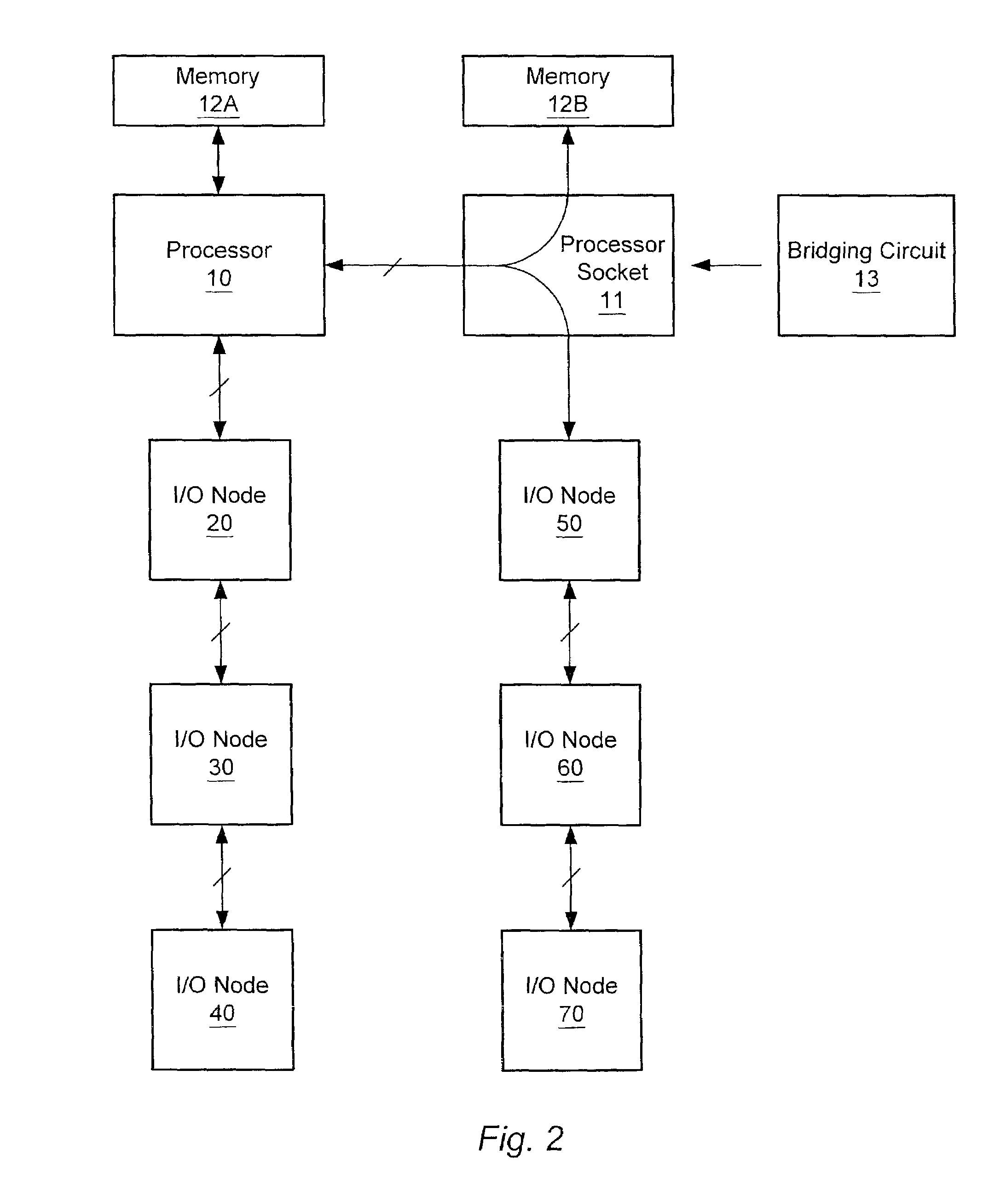
[0009]A method and apparatus for impedance matching in systems configured for multiple processors is disclosed. In one embodiment, a computer system includes a first processor socket and a second processor socket, each configured to accommodate a processor. The processor sockets may be electrically coupled to each other. A first I / O node may be electrically coupled to the first processor socket and a second I / O node may be electrically coupled to the second processor socket. A processor may be mounted in the first processor socket, while a bridging circuit may be mounted in the second processor socket. The bridging circuit may electrically couple the processor mounted in the first processor socket to the second I / O node, thereby allowing the computer system to utilize the I / O capability provided by the second I / O node even when a second processor is not present in the system. The bridging circuit may provide impedance matched signal paths between the processor and the second I / O node.

Problems solved by technology

Due to the clock frequencies of state-of-the-art system boards, it may be difficult to provide a connection between two buses across a processor slot.
Simple pin-to-pin electrical connections may be insufficient.
These pin-to-pin connections may be unable to match the impedances between the coupled signal lines.
The inability to match impedances between signal lines across a processor slot may result in the inability to utilize additional I / O, or may result in the need to redesign a system board.

Method used


Image

  • Method and apparatus for impedance matching in systems configured for multiple processors
  • Method and apparatus for impedance matching in systems configured for multiple processors
  • Method and apparatus for impedance matching in systems configured for multiple processors

Examples


Embodiment Construction

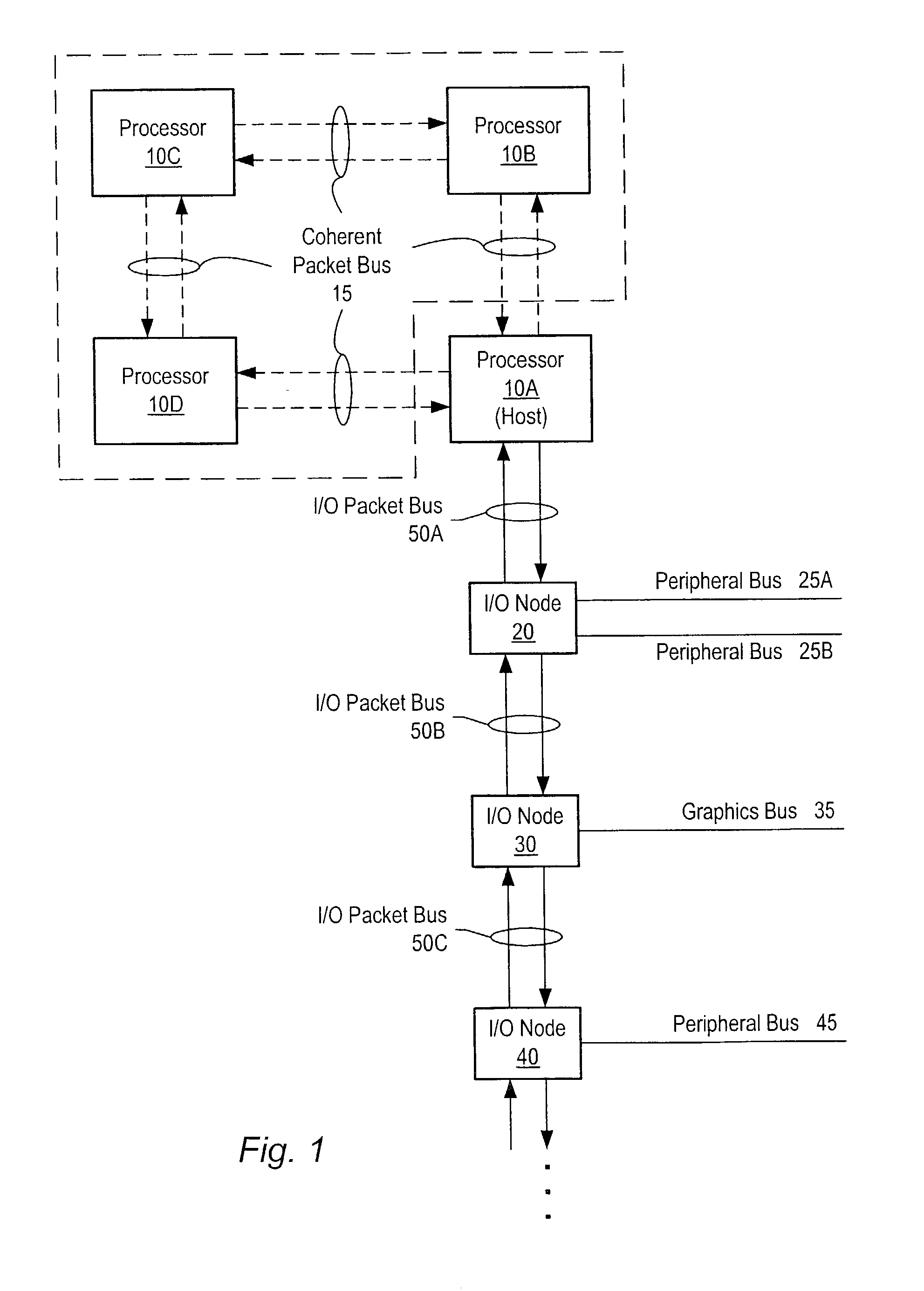
[0028]Turning now to FIG. 1, a block diagram of one embodiment of a computer system is shown. The computer system includes processors 10A–10D each interconnected by a coherent packet bus 15. Each section of coherent packet bus 15 may form a point-to-point link between each of processors 10A–D. While four processors are shown using point-to point links it is noted that other numbers of processors may be used and other types of buses may interconnect them. The computer system also includes three I / O nodes numbered 20, 30 and 40 each connected together in a chain by I / O packet buses 50B and 50C respectively. I / O packet bus 50A is coupled between host node / processor 10A and I / O node 20. Processor 10A is illustrated as a host node which may include a host bridge for communicating with I / O packet bus 50A. Processors 10B–D may also include host bridges for communication with other I / O packet buses (not shown). The communication links formed by I / O packet bus 50A–C may also be referred to a...


PUM


Abstract

A method and apparatus for impedance matching in systems configured for multiple processors is disclosed. In one embodiment, a computer system includes a first processor socket and a second processor socket, each configured to accommodate a processor. The processor sockets may be electrically coupled to each other. A first I / O node may be electrically coupled to the first processor socket and a second I / O node may be electrically coupled to the second processor socket. A processor may be mounted in the first processor socket, while an impedance matching circuit may be mounted in the second processor socket. The impedance matching circuit may electrically couple the processor mounted in the first processor socket to the second I / O node, thereby allowing the computer system to utilize the I / O capability provided by the second I / O node even when a second processor is not present in the system.

Description

BACKGROUND OF THE INVENTION[0001]1. Field of the Invention[0002]This invention relates to computer systems, and more particularly, to impedance matching mechanisms for systems that configured for multiple processors but having one or more processors not installed.[0003]2. Description of the Related Art[0004]Many computer systems, such as server systems, include system boards that are configured to support multiple processors. Such computer systems typically include multiple connectors (e.g. zero-insertion force, or ZIF sockets) to accommodate the multiple processors. In addition, computer systems configured for multiple processors may include multiple bus bridges and peripheral interfaces that may be intended to be dedicated to a single one of the processors when multiple processor are installed. This may greatly increase system throughput.[0005]Although many systems are configured to support multiple processors, such systems are often times shipped with only a single processor, or ...

Claims


Application Information

Patent Timeline
IPC IPC(8): H03K17/16
CPCH04L25/0278H05K3/222H05K1/0237H05K1/141H05K2201/10734H05K2201/09727H05K2201/10325
Inventor GULICK, DALE E.DOWLING, JONATHAN P.
Owner GLOBALFOUNDRIES INC
Learn More