
Synchronized primary winding current shunting technique for controlling electro-stimulus level

a primary winding current and electro-stimulus technology, applied in the field of electro-stimulus remote training collars, can solve the problems of undesirable welfare of the dog and the nearby people, general disturbance, undesirable low open circuit voltage between the stimulus electrode transformer and the stimulus electrode, etc., and achieve the effect of convenient adjustment of the stimulation intensity applied to the animal

Active Publication Date: 2006-02-21
GARMIN
View PDF8 Cites 26 Cited by
  • Summary
  • Abstract
  • Description
  • Claims
  • Application Information

AI Technical Summary

Benefits of technology

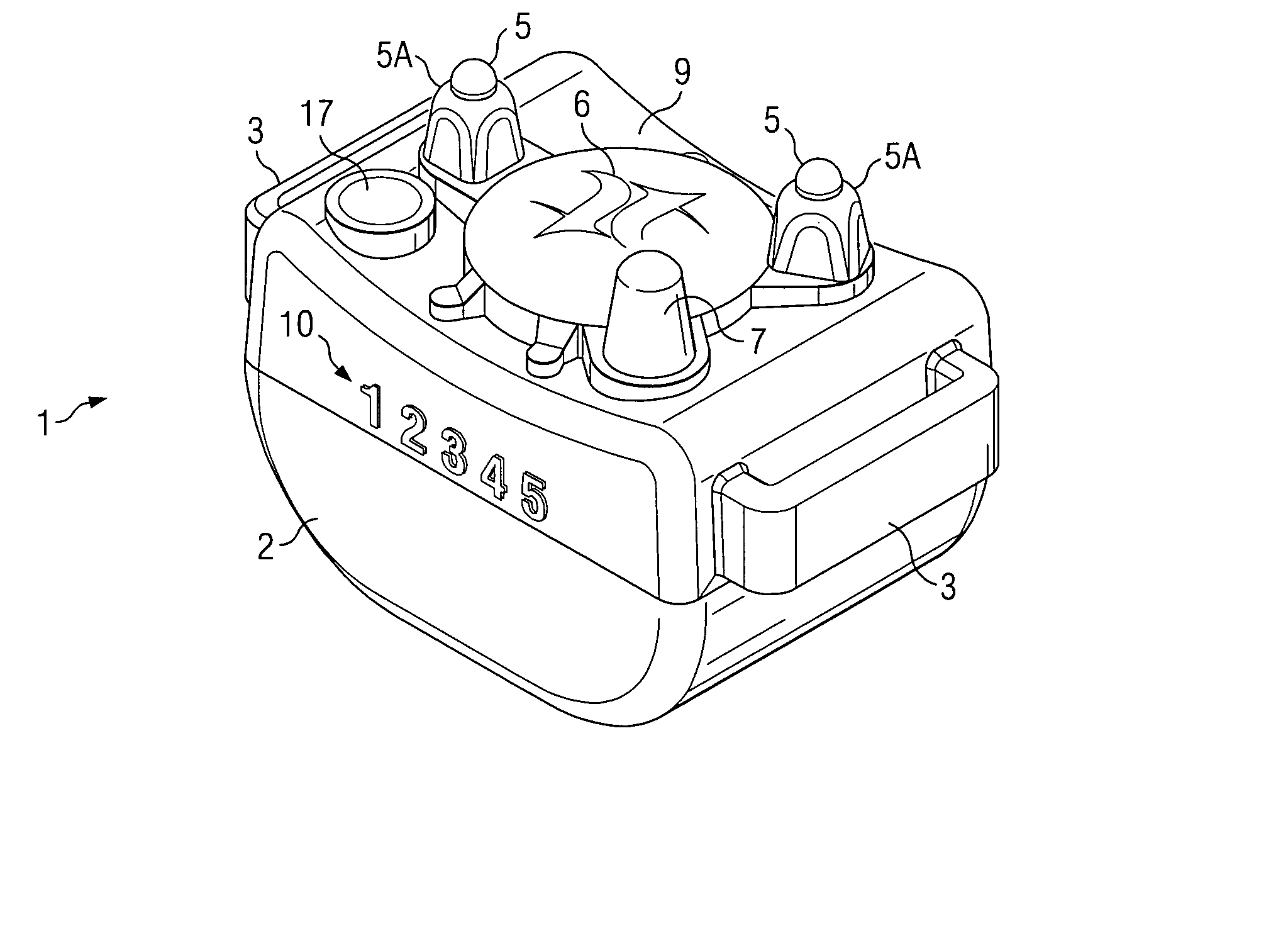
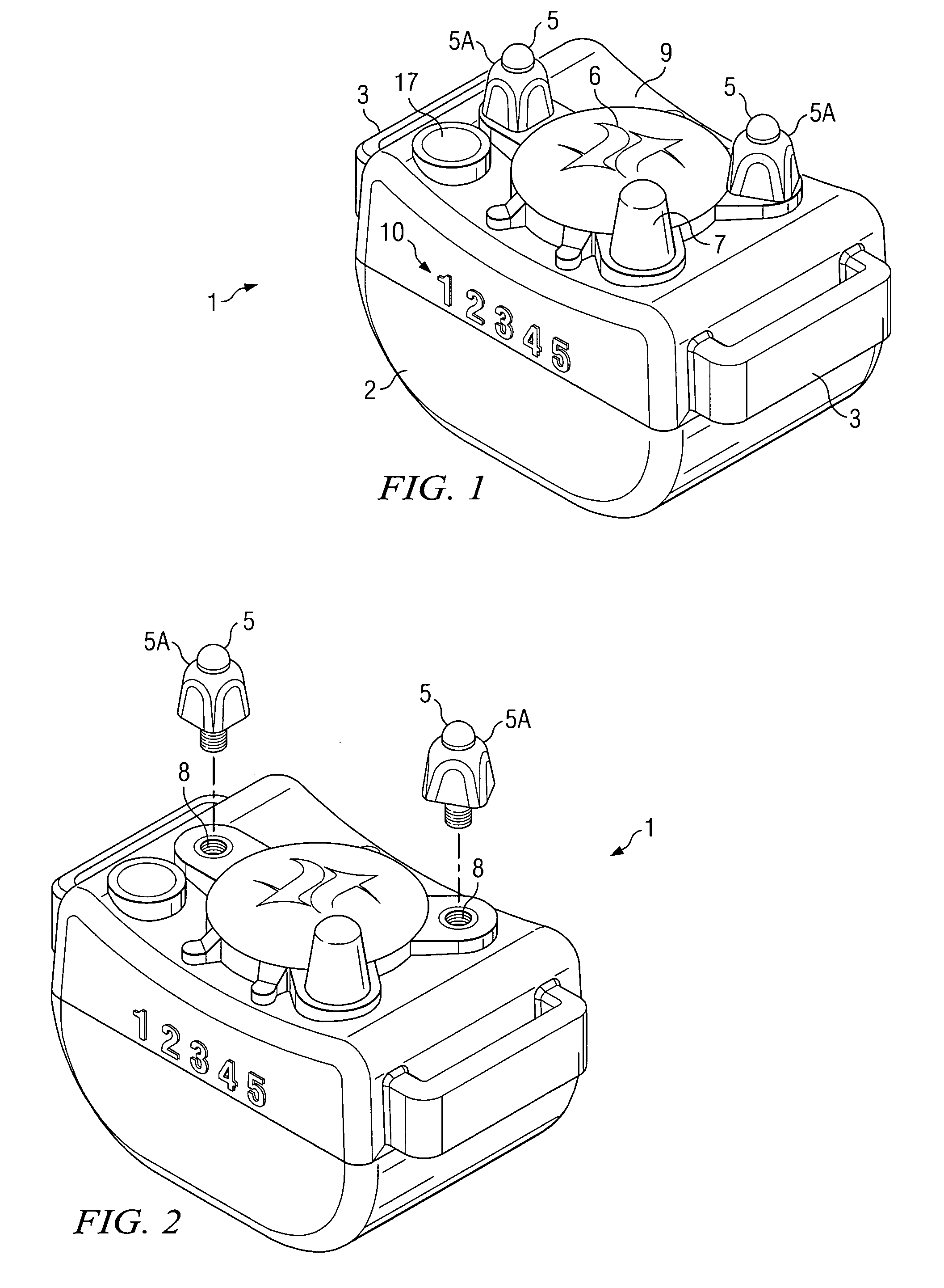
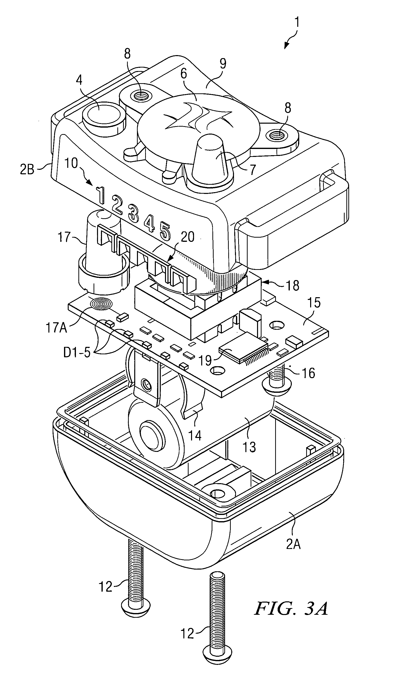
The present invention provides an improved animal training device that allows for convenient adjustment of the level of stimulation intensity applied to the animal. The device is small and lightweight, and can provide a high level of output voltage. It is designed to be worn by a small or tiny animal, such as a dog, and can effectively control barking. The device is also designed to reduce power consumption and avoid accidental stimulation of the animal. It includes a housing, first and second stimulus electrodes, a controller, and a switching transistor. The controller produces aversive stimulus control signals and the switching transistor produces bursts of current pulses in response to the controller's signals. The device can be adjusted to control the intensity of the aversive stimulus and can detect and synchronize with the animal's barking. It is also designed to be easily visible and can be worn by the animal.

Problems solved by technology

This is undesirable with respect to the welfare of the dogs themselves and nearby people.
Similar problems occur in neighborhoods in which there are dogs that are kept outside at night: if one dog starts barking others are likely to join in, causing a general disturbance.
However, the large size and weight of the assignee's Bark Limiter product have limited it to use on medium-sized and large-sized dogs.
This causes the peak open circuit voltage produced between the stimulus electrodes driven by the secondary winding of the output transformer to vary as a function of the selected / desired stimulus intensity, and sometimes results in undesirably low open circuit voltages between the stimulus electrodes transformer.
A problem of the prior art has been that the effectiveness of coupling the electro-stimulus energy to the dog is reduced as the amount of RMS energy applied to the primary winding of the output transformer is reduced in order to reduce the stimulus intensity level.
This reduces the reliability of the electrical contact between the stimulus electrodes and the skin of the dog's neck, and thereby reduces the effectiveness of the training or even causes the training to become counterproductive, and leads to over-tightening of collar straps by dog trainers and / or owners, which often causes chronic sores on the dog's neck.
The battery life of some prior bark limiters has been undesirably short, especially because dog owners often find it convenient to leave the devices in a “power on” condition for long periods of time, even during times when the dog is not likely to be barking.
Another shortcoming of the larger prior art bark control devices is that they are too large to use on a small or tiny dog.
Yet another shortcoming of prior bark control devices is that occasionally when the dog scratches with its hind foot, it unintentionally contacts the power switch and turns off the power of the bark control device.

Method used


Image

  • Synchronized primary winding current shunting technique for controlling electro-stimulus level
  • Synchronized primary winding current shunting technique for controlling electro-stimulus level
  • Synchronized primary winding current shunting technique for controlling electro-stimulus level

Examples


Embodiment Construction

[0049]To summarize, a preferred embodiment of a dog bark limiter of the present invention provides convenient manual adjustability of the applied stimulus level to be applied to the neck of the dog by means of a switch. The bark limiter also includes low power circuitry that improves the electrical stimulation scheme to provide adequately high open circuit voltage between the stimulus electrodes in a small, lightweight collar-mounted animal training product at both high and low selected stimulus levels. The described bark limiter includes a motion detector that detects characteristic motion of the dog's neck produced as a result of barking and in response automatically powers up the circuitry from a very low power stand by operating condition.

[0050]A technique of “valid” bark detection using software wherein a capture and compare routine is executed in software executed by a microcontroller to accomplish the function of, in effect, generating a frequency spectrum of the received sou...


PUM


Abstract

An electronic apparatus (1) for training an animal is supported against the animal's skin, and includes stimulus electrodes (5) for electrically contacting the skin. A controller including output terminals producing aversive stimulus control signals, a first switch (Q4) coupled to a winding to produce therein a burst of first current pulses in response to a first signal produced by the controller (33) and a second switch (Q2) coupled to the first switch (Q4) operative to synchronously shunt predetermined trailing portions of the first current pulses away from the winding in response to a second signal produced by the controller to reduce the amount of energy delivered to the winding by the switching transistor (Q4) without substantially changing a peak value of a flyback voltage across the winding. The controller sets various values of time intervals during which portions of the first current pulses are shunted away from the winding in order to set various corresponding intensities of aversive stimulus.

Description

BACKGROUND OF THE INVENTION[0001]The present invention relates generally to electronic remote training collars and the like and also to collar-mounted electronic “bark limiter” or dog bark training devices, and more particularly to improvements therein which reduce the size, weight and power consumption thereof without reducing the open circuit stimulus voltage, allow convenient manual adjusting of stimulus levels, provide improved sensing of what constitutes valid barking, provide low-power standby operation when the dog is not barking, and allow monitoring of the amount of valid barking that actually occurs.[0002]A variety of electronic dog training collars have been utilized for applying electrical shock and / or audible stimulus to a dog when it barks. In many situations it is highly desirable to prevent individual dogs or groups of dogs from barking excessively. For example, one dog's barking in a kennel is likely to stimulate other dogs to bark. This is undesirable with respect ...

Claims


Application Information

Patent Timeline
Patent Type & Authority Patents(United States)
IPC IPC(8): A01K15/02A01K15/04
CPCA01K15/022
Inventor NAPOLEZ, FRANCISCO J.DUNCAN, TIMOTHY T.CRIST, TIMOTHY J.ZAKHARYAN, KAGUM G.
Owner GARMIN
Learn More